check

check

check

check
Have you ever dreamed of creating your own 3D models without breaking the bank? Imagine transforming everyday objects into digital replicas using affordable, accessible tools. With the rise of DIY electronics, building a homebrew 3D scanner is now within reach, and it all starts with the ingenious combination of an Arduino microcontroller and an IR distance sensor. This project not only demystifies complex scanning technology but also opens doors to endless creative possibilities—from prototyping gadgets to archiving personal treasures. In this guide, we’ll dive into how to construct a functional 3D scanner leveraging Arduino and infrared sensors, ensuring every step is straightforward and rewarding for makers of all levels.
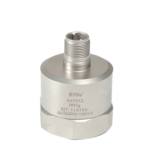
At its core, a 3D scanner captures the shape and dimensions of physical objects by measuring distances from multiple angles. Traditional laser scanners can be costly, but an IR distance sensor offers a budget-friendly alternative. These sensors emit infrared light and calculate distance based on how the light reflects back, much like how bats use echolocation. When paired with an Arduino board—a popular open-source platform—you can automate the scanning process for accurate 3D modeling. The result? A compact, low-cost system that rivals commercial options for simple applications. Before we jump in, let’s outline the essential components you’ll need: an Arduino Uno or similar board (around \(20), a reliable IR distance sensor such as the Sharp GP2Y0A21YK0F (priced under \)15), a stepper motor for precise rotational control, a turntable or platform, jumper wires, and basic mounting hardware. Software-wise, you’ll use the Arduino IDE for coding and free tools like MeshLab or Blender for processing the scanned data into 3D models. This setup keeps costs under $50, proving that innovation doesn’t have to drain your wallet.

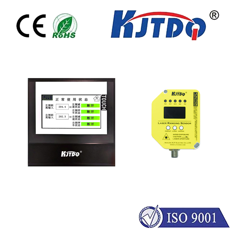
How does the scanning principle actually work? It begins with the IR distance sensor, which sends out an infrared beam and records the time it takes to bounce back. By converting this into distance measurements, the sensor feeds data to the Arduino via analog input pins. To build a full 3D image, we mount the sensor on a fixed arm while the object rotates on a turntable driven by the stepper motor. The Arduino coordinates this motion, step by step, capturing hundreds of distance readings at different angles. Think of it as taking a series of “depth slices” around the object—each measurement represents how far the surface is from the sensor at that point. As the turntable rotates incrementally (say, one degree per step), the Arduino logs all readings, which can later be stitched together into a point cloud. This point cloud is essentially a map of 3D coordinates, ready for conversion into a mesh model. The beauty of this approach lies in its simplicity; because IR sensors are unaffected by ambient light changes, they provide consistent, reliable scans for indoor projects. Plus, Arduino’s versatility allows easy customization, such as adjusting scan resolution or incorporating multiple sensors for faster captures.
Now, let’s walk through the assembly steps. First, securely mount your IR distance sensor on a stable frame—aim it directly at the object’s center on the turntable. Connect the sensor to the Arduino: typically, the VCC pin to 5V, GND to ground, and the output pin to an analog input like A0. Next, attach the stepper motor to the turntable using a driver module like the ULN2003, linked to the Arduino’s digital pins. Power everything with a 9V battery or USB supply to avoid interference. Calibration is crucial here: test the sensor’s range by placing objects at known distances and fine-tuning the code to ensure accuracy. Once hardware is set, upload the Arduino sketch. Start by initializing the motor and sensor in the setup function, then loop through rotation steps—for example, 360 steps for a full circle. In each iteration, read the sensor value, convert it to distance (using the sensor’s datasheet formula), and store it with the current angle. Sample code snippets might look simple, like distance = analogRead(A0) * conversion_factor;, but they form the backbone of your data collection. For enhanced precision, implement error handling, such as averaging multiple readings per angle to smooth out noise.
With data in hand, processing it into a 3D model is equally exciting. Export the logged angles and distances to a CSV file, then import it into free software. Tools like MeshLab can convert the point cloud into a textured mesh by connecting the dots algorithmically. The key advantage of this DIY setup is its adaptability: swap sensors or add cameras for color details, or scale it up for larger objects like sculptures. Applications abound—educators use it to teach physics and coding, hobbyists replicate artifacts, and tinkerers refine prototypes. One user shared how they scanned small engine parts for custom replacements, saving hundreds on professional services. Remember, success hinges on iterative testing; start with simple shapes like boxes to debug, then advance to complex contours. Always prioritize safety by avoiding rapid movements near the sensor.
In terms of optimization, frequently refine your code and calibration to boost scan quality. For instance, reducing motor vibration or shielding the sensor from stray infrared sources minimizes errors. Ultimately, this Arduino-based solution proves that powerful 3D scanning isn’t just for experts—it’s a gateway to innovation, empowering anyone to bring ideas to life digitally. Explore online communities for shared code libraries and troubleshooting tips, and soon you’ll be scanning with confidence.