check

check

check

check
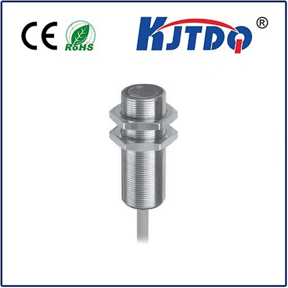
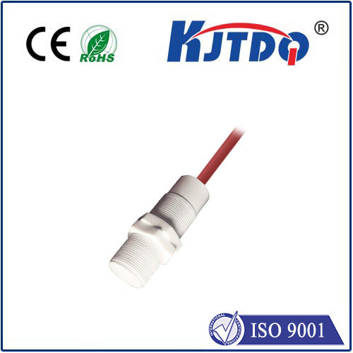
PNP Proximity Sensors: The Essential Guide to Features, Wiring & Industrial Applications
Imagine a bustling factory assembly line where robotic arms move with uncanny precision, seamlessly picking up components. Hidden within this intricate dance are countless silent sentinels: proximity sensors. Among the most prevalent and crucial types are PNP proximity sensors. But what exactly does “PNP” mean in this context, and why is this designation so vital for engineers and technicians? This guide dives deep into the world of PNP proximity sensors, explaining their operation, wiring, key differences, and the critical roles they play in modern automation.
Decoding “PNP”: It’s All About the Output Transistor
Contrary to its more general computing meaning (Plug and Play), “PNP” in the context of sensor proximity refers directly to the internal electronics driving the sensor’s output signal. Specifically, it indicates the use of a PNP-type bipolar junction transistor (BJT) as the output switching element within the sensor.
How PNP Proximity Sensors Work: Sourcing the Signal
Understanding the internal PNP transistor is key to grasping the sensor’s behavior:
Wiring Up a PNP Sensor: The Sourcing Connection
Wiring a PNP proximity sensor correctly is paramount for reliable operation. Think “Sourcing Sensor”:

Why Wiring Matters: The load (like a PLC input) needs the PNP sensor to provide the positive voltage when active. If you accidentally connected the load between the Black wire and positive supply, the sensor couldn’t energize it correctly – the load needs the positive side “fed” to it.
PNP vs. NPN: Understanding the Critical Distinction
The most common counterpart to the PNP proximity sensor is the NPN proximity sensor. Their fundamental difference lies in the type of internal output transistor and the resulting current flow:
PNP (Switched Positive / Sourcing):
Signal Output: Provides +V (e.g., +24V) when active.
Current Flow: Current sources from the sensor’s Signal wire, through the load, to 0V.
Load Connection: Load connects between Signal and 0V.
NPN (Switched Negative / Sinking):
Signal Output: Provides 0V (ground) when active.
Current Flow: Current sinks into the sensor’s Signal wire from the load, which is connected to +V.
Load Connection: Load connects between +V and Signal.
The Essential Differences at a Glance:
| Feature | PNP Proximity Sensor | NPN Proximity Sensor |
|---|---|---|
| Output Type | Switched Positive / Sourcing | Switched Negative / Sinking |
| Active State | Signal Output = +V Supply | Signal Output = 0V (Ground) |
| Current Flow | Sources current out of signal | Sinks current into signal |
| Common Load | PLC Sinking Input / Relay Coil | PLC Sourcing Input / Relay Coil |
| Wiring Mnemonic | “Load between Signal & 0V” | “Load between +V & Signal” |
Choosing the Right Sensor: The selection between PNP and NPN is primarily dictated by the input characteristics of the control system or load you are connecting the sensor to. Many modern PLCs accept both types via universal inputs, but legacy systems or specific modules might require one or the other. Always consult the specifications of both the sensor and the receiving device.
Key Advantages of PNP Proximity Sensors
Industrial Applications: Where PNP Proximity Sensors Shine
PNP proximity sensors are fundamental building blocks in countless industrial automation and control scenarios: