sensor inductive proximity
- time:2025-06-25 00:00:06
- Click:0
Inductive Proximity Sensors: The Essential Guide to Non-Contact Metal Detection
Imagine a high-speed bottling line. Bottles whizz by, perfectly positioned for filling and capping. This precision, often unseen but critical, frequently relies on a workhorse of industrial automation: the inductive proximity sensor. These robust, non-contact devices are ubiquitous in factories worldwide, silently detecting the presence or absence of metallic objects, ensuring processes run smoothly, safely, and efficiently. Understanding what they are and how they function is key to unlocking their potential in countless applications.
Demystifying the Core Principle: Faraday’s Law in Action
At the heart of every inductive proximity sensor lies the fundamental principle of electromagnetic induction, discovered by Michael Faraday. The sensor contains four key components:
- An Oscillator Circuit: Generates a high-frequency alternating current.
- A Coil (Inductor): This coil, typically wound around a ferrite core, creates a high-frequency electromagnetic field when energized by the oscillator. This field radiates out from the active sensing face of the sensor.
- A Target (The Object to Detect): A metallic object (ferrous like iron/steel, or non-ferrous like aluminum, brass, copper) entering this electromagnetic field.
- A Detection Circuit: Monitors changes in the oscillator’s behavior.
Here’s the magic: When a conductive metal target enters the sensor’s electromagnetic field, Eddy currents are induced on the surface of the target. These swirling currents create their own opposing magnetic field. This interaction damps the oscillation amplitude within the sensor’s coil. The detection circuit is finely tuned to sense this energy loss or change in oscillation. Once the damping reaches a predetermined threshold, the sensor’s output state switches (e.g., from OFF to ON, or vice versa, depending on its configuration). Crucially, no physical contact occurs between the sensor and the target.
Key Characteristics and Advantages: Why Choose Inductive?

Inductive proximity sensors offer a compelling set of features making them indispensable:
- Non-Contact Operation: Eliminates mechanical wear and tear on both the sensor and the target, ensuring long operational life and minimal maintenance. This is a major advantage over mechanical switches.
- High Reliability and Speed: Capable of detecting targets at incredibly high speeds (thousands of times per second) with remarkable repeatability. Excellent for counting or high-speed positioning.
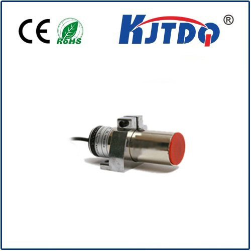
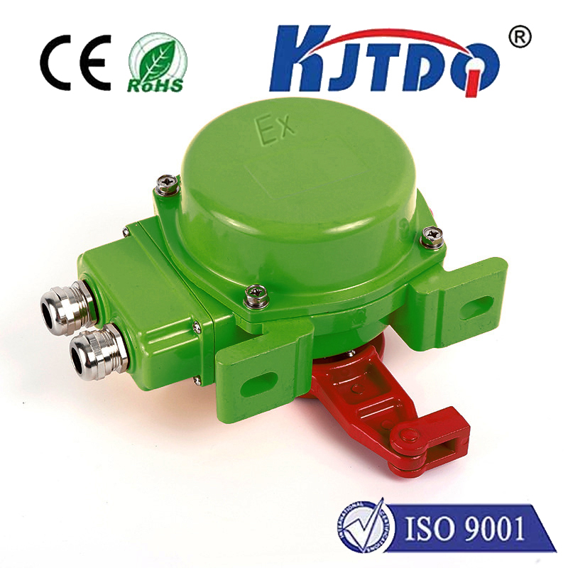
- Robust Construction: Typically housed in rugged metal (stainless steel, brass) or durable plastic bodies, making them highly resistant to dirt, dust, oils, coolants, and vibration. Many offer IP67 or IP68 ratings for harsh environments.
- Insensitivity to Surface Conditions: Generally unaffected by target surface dirt, moisture, or paint (as long as the target material itself is conductive). Focuses on the metal.
- Simple Installation and Use: Often require only power and load connections. No complex calibration needed for standard applications.
Understanding Crucial Specifications: Selecting the Right Sensor
Choosing the correct inductive proximity sensor hinges on several key parameters:
- Sensing Distance (Sn): The ideal, nominal distance at which the sensor is guaranteed to detect a standard target under defined conditions. Always refer to manufacturer datasheets. Never design your application to operate exactly at Sn; allow a safety margin.
- Operating Distance (Sa): The practical sensing range under actual operating conditions and temperature. It’s typically less than Sn.
- Target Material: Ferrous metals (iron, steel) are detected at the nominal sensing distance. Non-ferrous metals (aluminum, copper, brass) have a reduced sensing range, often 40-60% of Sn. Stainless steel detection range also varies based on grade. Always verify the sensor’s specifications for your specific target material.
- Switching Frequency: The maximum number of on/off cycles the sensor can handle per second. Critical for high-speed applications.
- Output Type: Common options include:
- NPN (Sinking)
- PNP (Sourcing)
- Normally Open (NO) / Normally Closed (NC)
- Analog (Current or Voltage proportional to distance)
- IO-Link (Digital communication for advanced diagnostics and configuration)
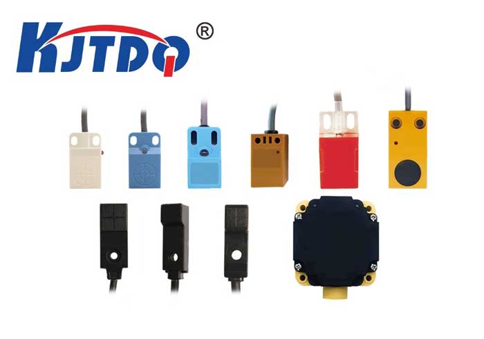
- Housing Shape & Size: Cylindrical (M8, M12, M18, M30 etc.) or rectangular blocks. Size impacts sensing range and installation space.
- Environmental Ratings: IP (Ingress Protection) rating for dust/water resistance and temperature range are vital for reliability in challenging conditions.
Table 1: Typical Sensing Range Reduction Factors (Approximate)
| Target Material |
Typical Sensing Range (vs. Mild Steel Sn) |
| Mild Steel (Fe360) |
100% (Sn) - Nominal Reference |
| Stainless Steel (304) |
70% - 90% of Sn |
| Brass (CuZn) |
50% - 70% of Sn |
| Aluminum (Al) |
40% - 60% of Sn |
| Copper (Cu) |
30% - 50% of Sn |
Diverse Applications: Where Inductive Proximity Sensors Shine
The robustness and reliability of inductive sensors make them suitable for a vast array of industrial and automation tasks:
- Position Verification: Confirming parts are present in fixtures, jigs, or at the end of a stroke (e.g., cylinder end position detection).
- Object Counting: Counting bottles, cans, packages, or machined parts on conveyors.
- End-of-Travel Detection: Monitoring the limits of moving parts like slides, doors, or robotic arms.
- Speed Monitoring: Detecting gear teeth, encoder discs, or rotating shafts for RPM measurement.
- Machine Safety: Integrating into safety circuits as part of guarding solutions (though specific safety-rated sensors are required for SIL/PL applications).
- Level Sensing: Detecting metal powders or liquids in tanks (using special designs).
- Metal Detection: Simple presence/absence checking of metallic parts in non-metallic carriers.
Best Practices for Optimal Performance
To maximize the effectiveness and lifespan of your inductive proximity sensors:
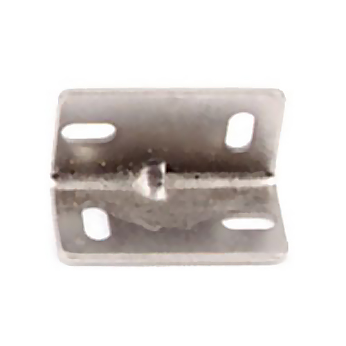
- Mount Securely: Ensure stable mounting to prevent vibration-induced false signals or damage.
- Respect Sensing Distances: Account for material reduction factors and include a safety margin (e.g., operate at 60-80% of Sn for reliable detection).
- Consider Flush vs. Non-Flush Mounting: Shielded (flush mountable) sensors can be embedded in metal without reducing range. Non-shielded (non-flush) sensors offer longer range but require an “escape zone” around the sensing face clear of surrounding metal.
- Mind the Environment: Choose the correct IP rating and temperature specification for your application. Shielded sensors are generally preferred in metallic environments.
- Check Target Size: The target should be at least equal to the sensor’s sensing face diameter for reliable detection at Sn. Smaller targets reduce the effective sensing range.
- Wire Correctly: Double-check voltage ratings, output type (NPN/PNP), and wiring polarity to avoid damage.
Evolving Capabilities: Beyond Simple Switching
While the core technology remains electromagnetic induction, modern inductive proximity sensors incorporate advanced features:
- Analog Outputs: Provide continuous distance information (e.g., 4-20mA, 0-10V), useful for position monitoring or gap measurement.
- IO-Link Communication: This point-to-point communication standard transforms simple sensors into smart devices. It enables:
- Remote configuration (e.g., adjusting switching points).
*