pnp no proximity sensor
- time:2025-06-19 01:12:37
- Click:0
Missing Your PNP Proximity Sensor? Practical Solutions for Industrial Automation
That moment when a critical machine grinds to a halt… lights flash, alarms blare, operators scramble. The culprit? A seemingly simple PNP proximity sensor that’s suddenly gone silent. It’s supposed to detect the presence or absence of an object from millimeters away, yet it refuses to acknowledge anything – a state known as “no signal,” “fails to detect,” or simply “PNP no proximity sensor.” This scenario isn’t just frustrating; it translates directly into costly downtime. Understanding why this happens and how to fix it swiftly is essential for maintaining smooth, efficient operations in factories, packaging lines, and countless automated processes.
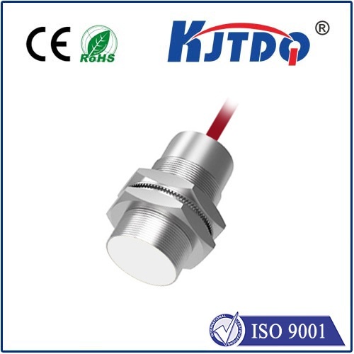
So, what exactly does “PNP no proximity sensor” signify? At its core, a proximity sensor is a workhorse of industrial sensing. It detects nearby metallic (and sometimes non-metallic) objects without physical contact, usually through electromagnetic, inductive, capacitive, or photoelectric principles. The PNP designation refers to its specific output configuration—the “sourcing” type. When an object is detected within its sensing range, a PNP sensor completes the circuit internally, connecting its signal wire (typically brown or black) to the positive supply voltage. This effectively sources +24V DC (the industrial standard) to the connected device, like a Programmable Logic Controller (PLC) input card. When nothing is detected, this connection is open, resulting in no voltage on the signal wire – the dreaded “no proximity sensor” state where the PLC sees an “off” condition.
When “PNP No Proximity Sensor” Strikes: Diagnosing the Silence
The sensor failing to send a signal when an object is present is the core failure mode. Here’s a structured approach to troubleshooting:

- Confirm Power Supply: It sounds basic, but start here.
- Verify the sensor has power. Check voltage between the positive supply wire (usually brown) and the negative/common wire (usually blue) directly at the sensor connector using a multimeter. It should read your system voltage, typically 24V DC ±10%. Low voltage is a common culprit.
- Ensure the power supply is stable and adequate, free from excessive noise or voltage dips.
- Inspect Wiring & Connections (The Usual Suspects):
- Physical Damage: Look for crushed cables, frayed wires, or damaged insulation near strain relief points or where wiring passes through panels.
- Loose Connections: Check connections at the sensor, any junction boxes, and the PLC input terminal. A loose wire on the signal or common line will cause failure.
- Shorts: Check for accidental shorts between the signal wire and positive supply or ground, which can damage the sensor output circuit or prevent a proper signal.
- Verify Object & Sensor Alignment:
- Is the target object actually within the rated sensing distance? Move it closer manually to test. Remember, sensing distance can be reduced for non-ferrous metals.
- Is the sensor properly aligned with the target? Misalignment is a frequent cause. Ensure the target approaches the sensor’s sensing face squarely.
- Is the target material compatible? Most inductive sensors detect ferrous metals best. Non-ferrous targets require sensors specifically rated for them. Check the sensor datasheet.
- Is there dirt, grime, paint, or buildup on the sensor face? Clean it thoroughly. Metal chips can also interfere.
- Check the Load & PLC Input:
- Load Compatibility: Ensure the PLC input module or other connected load can accept a PNP (sourcing) signal. Connecting a PNP sensor to an input designed for NPN (sinking) sensors won’t work. Understand your PLC input configuration.
- Load Resistance: While rare with modern sensors and PLCs, verify the load resistance isn’t too high, preventing the sensor from switching properly. Consult both sensor and PLC specs.
- PLC Input Status: Use the PLC programming software to monitor the specific input channel. Does it change state when you simulate a target? This helps isolate if it’s a sensor issue or a PLC input/cabling issue beyond the sensor.
- Sensor Fault & Environmental Factors:
- Physical Damage: Has the sensor been hit, bent, or exposed to severe impacts?
- Environmental Stress: Has the sensor been exposed to excessive vibration, temperatures outside its operating range, moisture ingress, or corrosive chemicals? These can cause internal component failure. PNP sensors are generally robust, but have limits.
- Internal Failure: Like any electronic device, the sensor’s internal circuitry can fail over time or due to a manufacturing defect or power surge. If all else checks out, a faulty sensor is likely.
- Electrical Noise: Strong electromagnetic interference near the sensor or its wiring can disrupt the signal. Check for proximity to motors, drives, or high-current cables. Ensure proper grounding/shielding. Using shielded cable properly terminated is crucial.
Implementing Solutions and Best Practices
Once the root cause is identified, implement the fix:
- Repair Wiring: Secure loose connections, replace damaged cables or connectors. Double-check wire colors and terminal assignments.
- Correct Power: Address under-voltage issues at the source. Ensure power capacity is sufficient.
- Clean & Align: Remove debris, clean the sensor face, and precisely realign the sensor to its target path.
- Replace Sensor: If damaged or internally faulty, replace it with an identical or equivalent model. Stick with reputable brands known for reliability.
- Address Environment: Relocate the sensor if possible, add protective shrouding, ensure proper sealing (IP rating), or choose a sensor designed for harsher conditions.
- Mitigate Noise: Reroute cables away from noise sources, ensure proper grounding of shields at one end only, use ferrite clamps if necessary. Verify sensor ground connection.
- Confirm PLC Compatibility: Double-check the PLC input specification and wiring matches the PNP sourcing requirement. Reconfigure input or sensor type if necessary.
- Preventative Maintenance: Schedule regular sensor cleaning and inspection, checking for secure mounting and cable wear. Document sensor locations and types.
PNP vs. NPN - Why It Matters
Understanding the difference between PNP (sourcing) and NPN (sinking) outputs is fundamental. Mixing them up is a prime reason for a “no signal” scenario. Remember:
- PNP (Sourcing): Output provides +24V when active. Connects to PLC inputs configured for sourcing signals (often labeled “positive logic” or “sourcing input”). Requires a common/negative connection.
- NPN (Sinking): Output connects to 0V/GND when active. Connects to PLC inputs configured for sinking signals (often “negative logic” or “sinking input”). Requires a positive supply connection.
Key Voltage Check Table When PNP Sensor Should Be Active:
| Point |
Measurement (Multimeter) |
Expected Value (24V System) |
Potential Problem Indicated |
| Power Supply |
Brown (+) to Blue (-) |
21.6V - 26.4V DC |
Low/High Voltage, No Power |
| Signal Output Active |
Black to Blue (-) |
~24V DC |
Sensor Not Detecting, Wiring Fault, PLC Input Issue |
| Signal Output Inactive |
Black to Blue (-) |
0V DC (or very low voltage) |
Normal Off State |
Proactive Steps to Minimize PNP Sensor Failures
Preventing “PNP no proximity sensor” downtime is better than troubleshooting it. Key proactive measures


