inductive sensor pnp - KJT
搜索

inductive sensor pnp

  • time:2025-06-19 00:00:07
  • Click:0

PNP Inductive Sensors: The Sourcing Solution for Industrial Proximity Detection

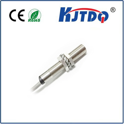
Imagine a factory floor humming with life. Robotic arms weld with precision, conveyor belts glide seamlessly, and packages are sorted at lightning speed. Hidden beneath this orchestrated chaos are countless unsung heroes ensuring everything happens safely and efficiently. Among the most crucial are inductive proximity sensors, specifically those with PNP output configurations. Understanding why PNP inductive sensors are often the preferred choice is key to optimizing modern industrial automation.

Demystifying Inductive Proximity Sensing

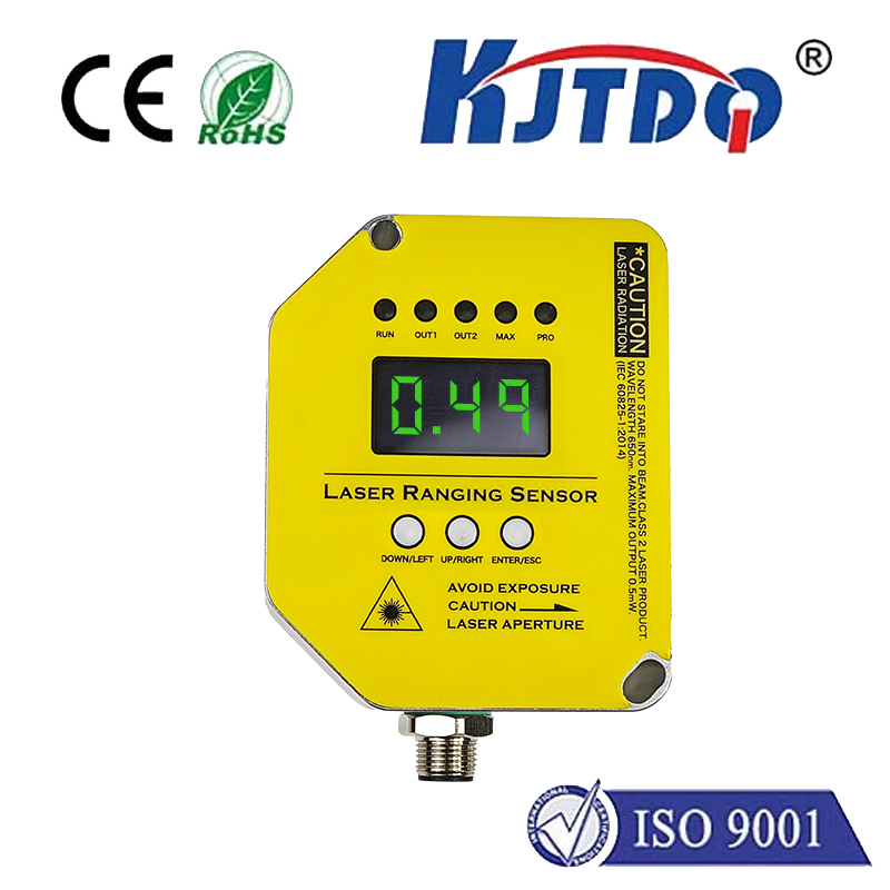
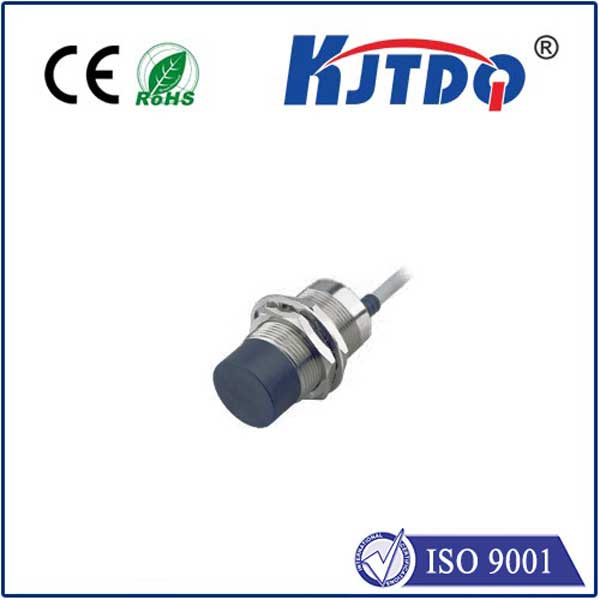
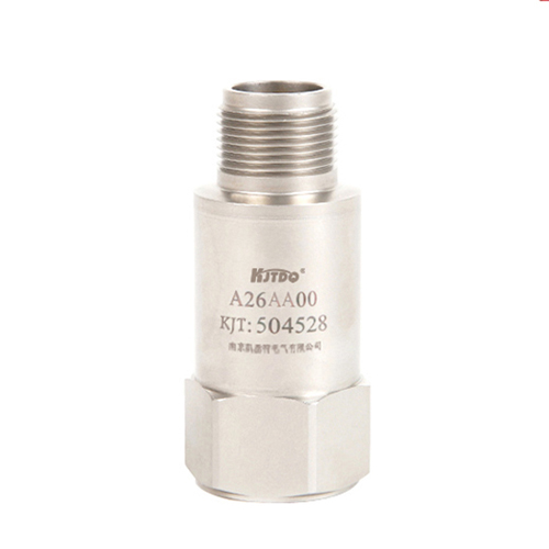
At their core, inductive proximity sensors are non-contact electronic devices designed to detect the presence or absence of metallic objects without physical touch. They operate on a fundamental electromagnetic principle:

  1. Generating the Field: The sensor’s active face contains a coil energized by an oscillator, creating a high-frequency alternating electromagnetic field.
  2. Target Interaction: When a conductive metal target (like steel, aluminum, brass, copper, etc.) enters this field, it induces small electrical currents within the target called eddy currents.
  3. Field Dampening: The creation of these eddy currents draws energy from the sensor’s oscillating field, causing it to dampen or reduce in amplitude.
  4. Signal Processing: An internal circuit continuously monitors the state of this oscillation. The dampening effect caused by the target’s presence triggers the sensor’s switching output.

This robust principle makes inductive sensors incredibly reliable for harsh industrial environments. They are immune to dust, oil, moisture (within their IP rating), vibrations, and can detect metal targets through many non-metallic materials. Common applications include position verification (is a part present?), end-of-travel detection (has the cylinder fully extended?), object counting, speed monitoring, and machine safety interlocks.

The Crucial Role of Output Configuration: Introducing PNP

Once the sensor detects a target, it needs to communicate this state change to the control system, typically a Programmable Logic Controller (PLC), motor drive, or counter. This is where the output configuration – PNP or its counterpart NPN – becomes critical.

PNP stands for “Positive-Negative-Positive,” referring to the type of bipolar junction transistor used in the sensor’s output stage. In simpler terms, a PNP sensor is a “sourcing” sensor.

Here’s what that means electrically:

  • Wiring: A typical 3-wire DC inductive proximity sensor has:

  • Brown (or Red) Wire: Connected to the positive supply voltage (typically +24V DC).

  • Blue Wire: Connected to the negative supply voltage (0V DC / Ground).

  • Black Wire: The output signal wire.

  • PNP Output Behavior:

  • No Target Present: The output transistor is OFF. The black wire is electrically disconnected from the internal positive supply (brown wire). It’s in a high-impedance state, effectively “floating”. No current flows out of the black wire.

  • Target Present: The output transistor switches ON. This connects the black wire internally to the positive supply voltage (+24V DC). The sensor sources positive current out of the black wire and into the load (e.g., the PLC input).

Why PNP Often Takes the Lead in Industrial Settings

While both PNP and NPN sensors are valid and widely used, PNP configurations tend to dominate in many industrial regions (like Europe and North America) for several practical reasons:

  1. Compatibility with Sinking PLC Inputs: The vast majority of industrial PLCs manufactured for these markets are designed with sinking digital inputs. A sinking input expects to receive positive voltage (current flowing into it) to register an “ON” signal. The PNP sensor’s sourcing output is a perfect match for these sinking PLC inputs. Connecting the PNP output (black wire) directly to the PLC input, with the PLC input’s common connected to 0V, creates the required current flow path. This plug-and-play compatibility significantly simplifies wiring and reduces commissioning errors.
  2. Simplified Fault Finding: When a PNP sensor is active (target present), it sources +24V onto its output wire. This voltage is relatively easy to measure with a standard multimeter referenced to 0V. If the sensor is active but no voltage is present on the output wire, the fault (open circuit, blown fuse, wiring break) is usually faster to locate compared to tracing missing ground paths.
  3. Safety Philosophy (Debated but Prevalent): Some safety philosophies prefer that a loss of power (e.g., 0V wire break) in a critical stop circuit causes the signal to go low (0V), mimicking the “no target” or “stop” state. In certain wiring configurations, PNP outputs can align more naturally with this “de-energize to stop” safety concept for non-safety-rated sensors, though this is nuanced and depends heavily on the specific circuit design. Crucially, functional safety always requires certified safety devices designed explicitly for the purpose.
  4. Prevailing Standards and Practices: Historical adoption and widespread use of sinking PLC inputs have created a strong ecosystem where PNP sensors are the default choice in many factories and machine designs. This standardization simplifies inventory management and technician familiarity.

Selecting the Right PNP Inductive Sensor

Choosing the optimal PNP inductive sensor goes beyond just the output type. Key considerations include:

  • Sensing Range: The maximum distance at which the sensor can reliably detect the target material. Always refer to the rated operating distance (Sn) for the specific metal. Ferrous metals (like steel) have longer ranges than non-ferrous metals (like aluminum).
  • Target Material: Confirm the sensor is suitable for your application metal. Some sensors are optimized for ferrous-only, others for non-ferrous, and some are “factor 1” meaning their range is minimally affected by the target material type.
  • Housing Material & Style: Choices include threaded barrels (M8, M12, M18, M30 are common), rectangular blocks, or specialized shapes. Material options include nickel-plated brass or stainless steel for corrosion resistance.
  • Output Type: PNP is our focus, but also specify Normally Open (NO - output ON when target present) or Normally Closed (NC - output OFF when target present).
  • Connection: Pre-wired cables, quick-disconnect (M12 connector being extremely common), or terminal blocks.
  • Environmental Rating (IP Code): Essential for dust and water resistance. IP67 (submersible temporarily) is a common industrial standard; IP68/IP69K offers even higher protection for washdown or extreme environments.
  • Electrical Specifications: Operating voltage range (typically 10-30V DC), switching current capacity, and voltage drop.
  • Special Features: Shielded (flush mountable) vs. Unshielded (longer range, requires side clearance), IO-Link capability for advanced diagnostics and parameterization, high-temperature resistance, resistance to welding fields, or food-grade housing.

The Sourcing Powerhouse for Reliable Detection

From ensuring robotic arms grip components correctly to guaranteeing safety guards are in place, PNP inductive sensors form an indispensable link in the industrial automation chain. Their inherent robustness, combined with the sourcing output configuration that aligns seamlessly with the prevalent sinking PLC inputs, makes them a logical and powerful choice. Understanding the distinction between PNP (sourcing) and NPN (sinking) is not just technical jargon; it’s fundamental to designing efficient, reliable, and easily maintained control systems. When metal detection reliability is paramount in demanding environments, the sourcing power of the inductive sensor PNP continues to be a

Recommended products