check

check

check

check
check

check
check
check
check
check
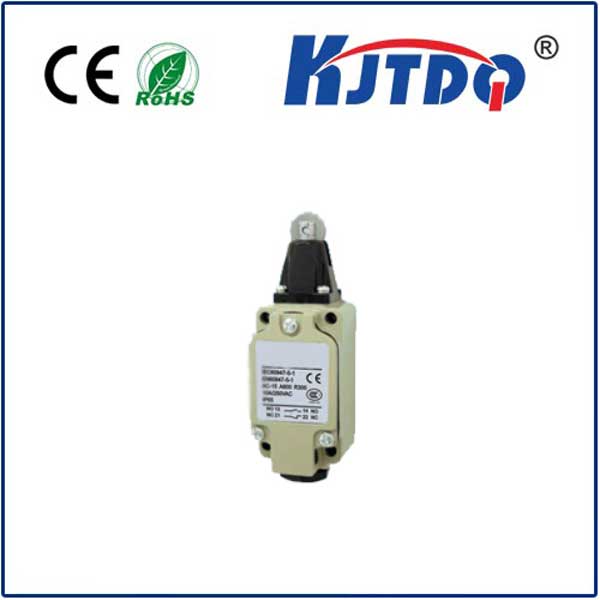
Imagine a massive excavator arm halting its movement with pinpoint accuracy exactly where the operator intends. Or picture a heavy industrial press stopping its descent precisely millimeters above the workpiece, cycle after cycle. This level of reliable, repeatable positional control in demanding hydraulic systems often hinges on a deceptively simple yet critical component: the hydraulic limit switch valve.
This specialized device acts as the interface between hydraulic force and electrical signals, providing crucial position feedback within a fluid power circuit. It’s not just a valve; it’s a robust position sensor tailor-made for the rugged world of hydraulics. Understanding its function and advantages is key for engineers and maintenance professionals designing or troubleshooting systems requiring accurate end-of-stroke detection or intermediate position control.
The Problem: Knowing “Where” in the Hydraulic World
Hydraulic cylinders provide immense power for linear motion, driving everything from construction equipment and agricultural machinery to factory automation and material handling systems. However, purely hydraulic systems lack an inherent, easy way to electronically signal when a cylinder piston has reached a specific point in its stroke. While external sensors (like proximity switches or LVDTs) are common, they can be vulnerable to environmental factors like extreme temperatures, dirt, shock, vibration, moisture, and electromagnetic interference – conditions frequently found where hydraulics operate.
The Hydraulic Solution: Where Fluid Flow Meets Electrical Signal

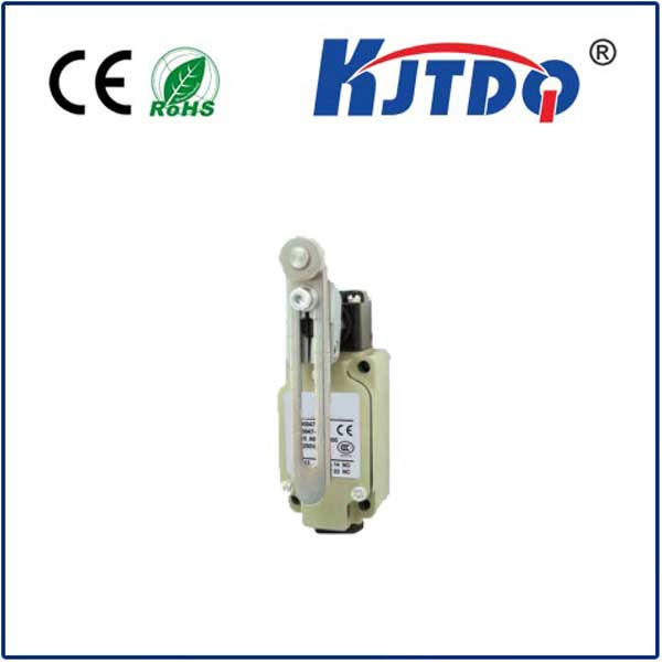
Enter the hydraulic limit switch valve. This clever device solves the sensing challenge by integrating the position detection mechanism directly into the hydraulic circuit. Its core function is straightforward: it gets mechanically actuated by the movement of the hydraulic cylinder itself (typically via a cam or striker mounted directly on the cylinder), and this physical actuation triggers an electrical switch.
How It Works: Simplicity in Action
Core Advantages: Why Choose a Hydraulic Limit Switch Valve?
The elegance of this design translates into significant operational benefits:
Key Applications: Where Precision Meets Power
Hydraulic limit switch valves are indispensable across numerous sectors:
Selecting the Right Valve:
Considerations include required switching function (NO/NC/SPDT), electrical rating (voltages and current), pressure rating, port sizes, actuator type (roller plunger, straight plunger), temperature range, and ingress protection (IP) rating. Connection types (DIN connectors, flying leads, terminal boxes) and robust mechanical construction for the mounting environment are also crucial.
The Unsung Hero of Control
While they might not be the most glamorous components, hydraulic limit switch valves are fundamental to achieving reliable, precise, and robust position control in countless hydraulic applications. By seamlessly converting mechanical cylinder position into a clear electrical signal within the protective envelope of the hydraulic system itself, they offer an integrated approach superior in harsh conditions. For engineers seeking dependable end-of-stroke confirmation or intermediate position feedback where reliability is paramount, this valve remains an often-overlooked but essential workhorse. It quietly ensures machines operate accurately, safely, and efficiently, cycle after demanding cycle.