rotary travel limit switch
- time:2025-09-13 00:58:19
- Click:0
Unlocking Precision Control: The Essential Guide to Rotary Travel Limit Switches
In the intricate dance of industrial automation, machinery, and heavy equipment, knowing precisely where things are – and where they should stop – is non-negotiable. Think of the massive arm of an overhead crane reaching its designated position, a conveyor belt halting perfectly at the loading station, or a dam gate stopping at the exact safe height. This critical control over movement limits and positions is often governed by an unassuming yet vital component: the rotary travel limit switch.
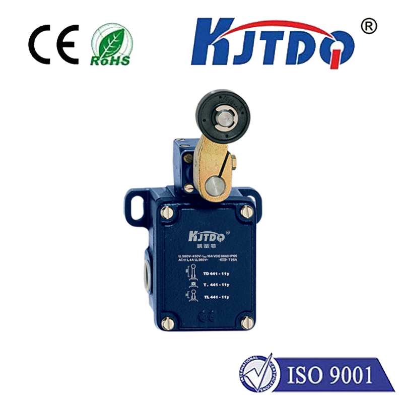
So, what exactly is a rotary travel limit switch? At its core, it’s a robust electromechanical device designed to monitor the rotary position of a shaft, wheel, or gear and initiate electrical control signals when predetermined angular positions are reached. Unlike linear limit switches that sense straight-line travel, rotary travel limit switches excel at tracking rotational movement, offering reliable and often highly repeatable position feedback.
How Does a Rotary Travel Limit Switch Work? It’s All About the Cam
The fundamental principle relies on a simple but effective mechanical interaction:
- Rotational Input: The device is mechanically linked to the rotating part of the machinery it monitors (e.g., via a chain, gear, or direct coupling to a shaft). As this part turns, the input shaft of the rotary travel limit switch rotates proportionally.
- Cam Activation: Mounted onto this input shaft is a series of adjustable cams. These cams are precisely set to specific angular positions corresponding to the desired start, stop, or intermediate control points in the machinery’s travel path.
- Electrical Switching: As the shaft rotates, the cams engage with operating levers or plungers attached to electrically independent snap-action switches housed securely within the switch enclosure. When a cam reaches its set point, it physically actuates the lever or plunger.
- Signal Change: This mechanical actuation causes the snap-action switch contacts to change state (e.g., from Normally Open (NO) to Closed (NC), or vice versa). This change in the electrical circuit sends a clear signal to the machine’s control system – effectively saying “Position Reached!” or “Stop Now!”.
Key Components & Design Advantages

Understanding the components highlights why rotary limit switches are chosen for demanding applications:
- Robust Housing: Typically constructed from die-cast metal (aluminum, zinc) or hardened plastics, offering superior protection against environmental hazards like dust, moisture (IP67 ratings common), oil, chemicals, and significant impact (IK ratings).
- Adjustable Cams: The heart of precision. Cams can be individually positioned around the shaft using locking mechanisms or gears, allowing for highly customizable trip points. Repeatability is a key metric, indicating how consistently the switch actuates at the same position on repeated cycles.
- Snap-Action Switches: Provide fast, positive switching action, minimizing arcing and ensuring reliable electrical contact even in high-vibration environments.
- Input Shaft: Designed for direct drive or connection via linkage to the monitored mechanism. Bearings ensure smooth operation and longevity.
- Multiple Contact Blocks: Crucial for complex control sequences, a single rotary travel limit switch can house several independently adjustable switches, enabling multiple control actions (e.g., slow down, warning signal, stop) at different angular positions during one rotation. Configurations often include SPDT (Single Pole, Double Throw) contacts.
Where Do Rotary Travel Limit Switches Shine? Key Applications
Their reliability, adjustability, and toughness make them indispensable across numerous sectors:
- Material Handling: Controlling travel limits and positions on overhead cranes, gantry cranes, hoists, elevators, stacker-reclaimers, and automated guided vehicles (AGVs).
- Conveyor Systems: Starting/stopping conveyors, indexing products, positioning diverters, and controlling accumulation zones.
- Construction Equipment: Monitoring boom angle, winch spooling limits, and platform positioning on excavators, cranes, and lifts.
- Valve Actuation: Providing position feedback (open/closed/partially open) for large valves in process control (water treatment, chemical plants, oil & gas pipelines).
- Industrial Doors & Gates: Controlling the open and close limits of hangar doors, bay doors, and security barriers.
- Renewable Energy: Tracking the rotational position in solar tracker systems and wind turbine pitch/yaw control.
- Packaging Machinery: Precise positioning for filling heads, sealing jaws, and labeling stations.
Why Choose a Rotary Travel Limit Switch? The Compelling Advantages
In a world of diverse sensors, why opt for this mechanical stalwart?
- Harsh Environment Tolerance: Unmatched durability in dirty, wet, oily, high-vibration, and extreme temperature conditions where optical or proximity sensors might fail.
- High Repeatability & Accuracy: Offers consistent and precise position detection once calibrated.
- Direct Mechanical Feedback: Provides unequivocal position verification through physical contact, immune to electrical noise that can plague purely electronic sensors.
- Intrinsic Safety: Often suitable for hazardous locations due to lack of electronics requiring power at the sensing point (in simple configurations).
- Multiple Control Functions: A single device with multiple adjustable cams can replace several individual limit switches, simplifying wiring and reducing installation points.
- Visual Indication: Often includes a position pointer and scale, allowing operators to visually verify settings or approximate position.
- Cost-Effectiveness: Proven technology offering excellent value, especially for demanding applications requiring robustness and multiple signals.
- Fail-Safe Operation: Can be configured to default to a safe state (e.g., open circuit stopping motion) in case of certain failures.
Selecting the Right Rotary Travel Limit Switch: Key Considerations
Choosing effectively requires evaluating several factors:
- Rotation Range: How many degrees of rotation need to be monitored? (e.g., 90°, 180°, 360°, multi-turn).
- Number of Control Points Needed: How many distinct positions require a signal? This determines the number of adjustable cams/switches required.
- Electrical Ratings: Ensure voltage, current (AC/DC), and contact ratings (resistive/inductive loads) match the control circuit requirements.
- Environmental Protection (IP Rating): Match the IP rating to the severity of the environment (dust, water jets, immersion).
- Impact Resistance (IK Rating): Important for locations prone to knocks or falling debris.
- Operating Speed: Ensure the switch can handle the rotational speed of the input shaft without premature wear.
- Mounting & Drive: Consider how the switch will be physically mounted and connected to the rotating element (direct shaft, chain sprocket, gear).
- Repeatability: The specified tolerance for position accuracy on repeated operations. Critical for precision tasks.
Beyond Basic Control: The Enduring Relevance
While newer sensor technologies emerge, the fundamental benefits of simplicity, robustness, visual verifiability, and multi-point control ensure the rotary travel limit switch remains a cornerstone of industrial automation. They provide a physically tangible and highly reliable solution for position sensing and travel limitation where adverse conditions, high reliability, and cost-effectiveness are paramount. Whether ensuring safety on a towering crane or guaranteeing precise filling levels on a production line, these electromechanical workhorses continue to deliver indispensable control, rotation after rotation.


