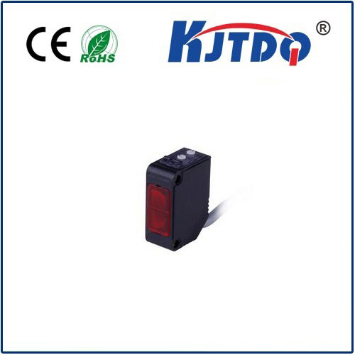
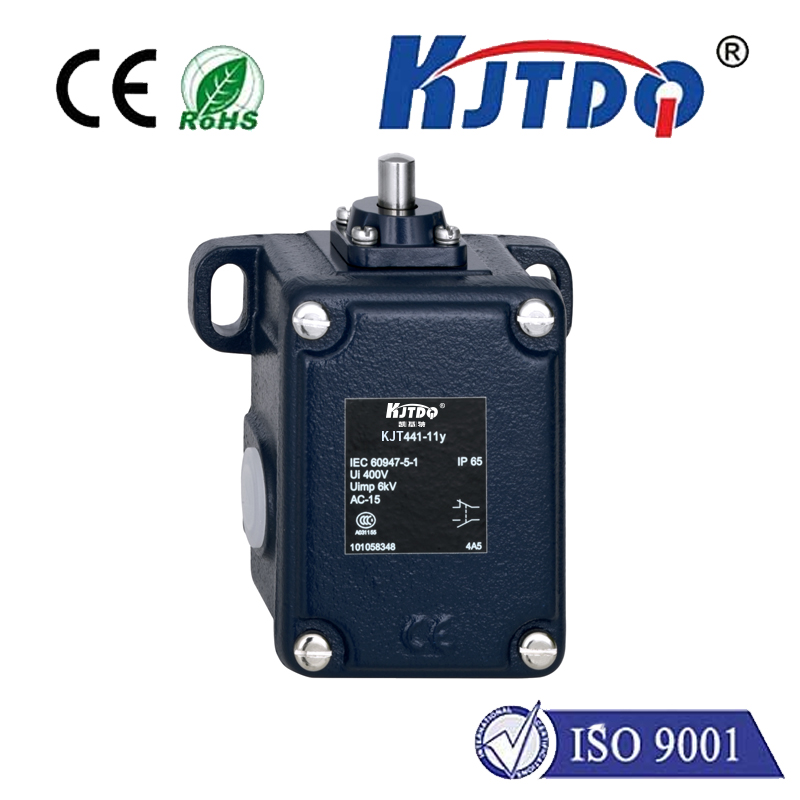
photoelectric sensor with relay
- time:2025-09-10 18:20:57
- Click:0
Bridging Detection and Action: The Essential Role of Photoelectric Sensors with Relays
Imagine a factory conveyor belt humming efficiently. Boxes zip by, each needing precise sorting or counting. A tiny device silently “sees” each passing box. But how does that simple detection translate into stopping the belt, activating an arm, or triggering an alarm? The answer lies in a powerful, often understated partnership: photoelectric sensors seamlessly integrated with control relays. This combination forms the bedrock of countless industrial automation tasks, transforming a basic signal into decisive action. Understanding how these components work together unlocks the door to designing smarter, more responsive systems, from simple presence checks to complex material handling solutions.
The Core Detectives: Understanding Photoelectric Sensors
At their heart, photoelectric sensors are non-contact detection devices. They operate on the principle of light emission and reception. Typically, they consist of:
- An Emitter: Produces a beam of light (infrared, visible red, laser).
- A Receiver: Detects the emitted light.
How the sensor reacts depends on its configuration and the object interrupting (or reflecting) the light beam. The three primary operating modes are:
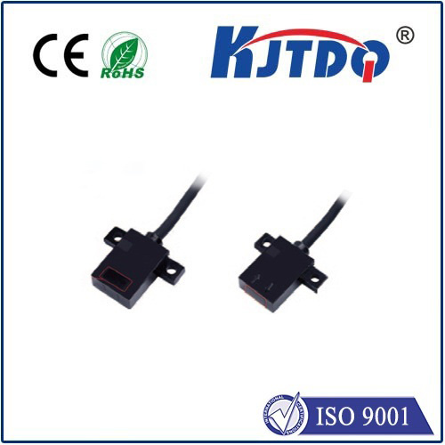
- Through-Beam (Opposed Mode): Emitter and receiver are placed facing each other. An object is detected when it breaks the beam path between them. Renowned for long sensing ranges and high reliability.
- Retroreflective (Reflective Mode): Emitter and receiver are housed together. A reflector opposite the sensor bounces the light back. An object is detected when it blocks the light from reaching the reflector. Offers simpler installation than through-beam.
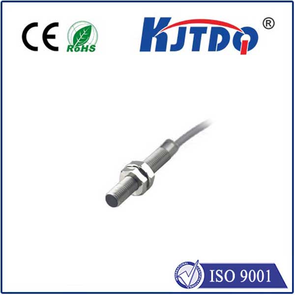
- Diffuse (Proximity Mode): Both emitter and receiver are in the same housing. Light reflects off the target object itself. Detection occurs when reflected light intensity reaches a certain threshold. Excellent for detecting objects without a reflector, though range is shorter and performance can vary with object color/surface.
The critical output of a photoelectric sensor is typically a simple electrical signal: ON (Light received / Object detected) or OFF (No light received / No object), depending on the sensor’s logic (Light-ON/Dark-ON). However, this signal is usually a low-current (+24 VDC is common) DC signal designed for logic circuits, not for driving high-power loads like motors, solenoids, or large lights. This is where the control relay becomes indispensable.

The Power Bridge: The Indispensable Role of Relays
A control relay is an electromechanical switch. Its primary function is to use a relatively small electrical signal (like the one from a photoelectric sensor) to control a much larger electrical current or voltage in a separate circuit. Think of it as an intermediary or an amplifier.
Here’s the breakdown of its operation:
- Coil: Receives the low-power signal from the photoelectric sensor. When energized (sensor output ON), it creates a magnetic field.
- Contacts: The magnetic field pulls internal switch contacts together (or apart, depending on the relay design). These contacts are rated to handle significantly higher current and voltage than the sensor output could manage.
- Isolation: Crucially, the coil circuit (low power) and the contact circuit (high power) are electrically isolated. This protects the sensitive sensor electronics from potential voltage spikes, noise, or high currents in the load circuit.
When a photoelectric sensor detects an object and activates, its output energizes the relay’s coil. The relay coil closes (or opens) its contacts, which are wired to the much more powerful load (a motor starter, a solenoid valve, a warning lamp, etc.). The sensor directs the when, the relay handles the heavy lifting.
Why Integrate? The Compelling Synergy
The marriage of photoelectric sensors and relays isn’t arbitrary; it solves critical challenges in industrial control:
- Interface Mismatch: Photoelectric sensors output low-current DC signals. Most actuators (motors, valves) require high-power AC or DC. The relay bridges this power gap effortlessly.
- Electrical Isolation: Relays provide vital electrical separation between the sensor’s delicate control circuitry and potentially noisy or high-voltage power circuits. This significantly enhances system reliability and longevity, protecting the sensor from damage.
- Logic Expansion: A single relay often has multiple contacts (NO - Normally Open, NC - Normally Closed). This allows one sensor signal to potentially control several independent loads simultaneously or create basic logic combinations (e.g., energize one device while de-energizing another upon detection).
- Safety Enhancement: Using a relay allows designers to utilize sensors operating at lower, safer control voltages (like 24VDC) while controlling potentially dangerous mains voltage (120VAC, 240VAC) loads via the relay contacts.
- Versatility: Relays are incredibly adaptable. The same photoelectric sensor and relay pair can control vastly different loads just by rewiring the relay contacts.
Bringing Theory to Life: Common Applications
The practicality of photoelectric sensors with relays shines in numerous everyday automation scenarios:
- Conveyor Object Counting & Sorting: A sensor detects each package. Its signal triggers a relay that momentarily activates a diverter arm or increments a counter.
- Level Detection in Tanks/Bins: A sensor aimed across a bin detects when material reaches a certain level (interrupting the beam). This activates a relay, stopping a filling motor or starting an emptying pump.
- Automatic Door Control: A sensor detects a person approaching. Its output energizes a relay that powers the door-opening mechanism.
- Packaging Machinery: Sensors ensure labels are present, products are correctly positioned, or cases are sealed. Missing components trigger relays to halt the machine via a safety circuit or activate an alarm beacon.
- Material Handling Gates: Sensors detect the presence of a pallet at a specific location. This triggers a relay to lock or unlock a gate mechanism.
- Simple Production Counters: Each detected part activates a relay contact configured to pulse an electronic counter display.
Selecting the Right Components: Key Considerations
Successful implementation hinges on choosing suitable partners:
- Photoelectric Sensor Selection:
- Operating Mode: Through-beam, Retroreflective, or Diffuse based on the application’s range, mounting constraints, and object properties.
- Sensing Range: Ensure sufficient distance for reliable detection.
- Output Type: Almost exclusively Discrete Output (ON/OFF). Confirm if NPN (Sinking) or PNP (Sourcing) output is compatible with your relay coil input requirements.
- Environmental Factors: IP rating for dust/moisture protection, resistance to vibration or chemicals.
- Power Supply: Matching voltage (e.g., 10-30 VDC).
- Relay Selection:
- Coil Voltage/Current: Must match the sensor’s output type and specifications. Using a 5VDC relay coil with a sensor providing 24VDC PNP output will damage the relay.
- Contact Rating: Critical! The contacts must handle the voltage (AC or DC?) and the amperage (current) required by the connected load (motor, lamp, solenoid). Always choose a relay with contact ratings exceeding the load requirements for safety and longevity.
- Contact Configuration: How many poles (sets of contacts)? How many Normally Open (NO) or Normally Closed (NC) contacts do you need?
- **Mount