proximity sensor pnp
- time:2025-09-09 04:06:34
- Click:0
PNP Proximity Sensors: The Sourcing Solution for Reliable Object Detection
Have you ever considered the unseen technology ensuring your car door locks engage, a factory conveyor stops precisely, or your smartphone screen dims during a call? Often hidden from view, proximity sensors are the silent guardians of automation and reliability. Among the diverse range available, the PNP proximity sensor stands out as a particularly prevalent and vital configuration, especially in many industrial settings. Understanding its operation, advantages, and typical applications is key to leveraging its capabilities effectively.
At its core, a proximity sensor (inductive type being most common for metal detection) works by emitting an electromagnetic field. When a metallic object enters this field, it induces eddy currents within the object, altering the sensor’s internal oscillator circuit. This change is detected, triggering an output state change. Crucially, this output needs to interface with control systems like Programmable Logic Controllers (PLCs), and this is where the PNP vs. NPN distinction becomes paramount. It defines how the sensor’s output signal is electrically connected and switches relative to the power supply.
So, what makes a sensor PNP? The acronym stands for Positive-Negative-Positive. This refers to the type of transistor – a PNP transistor – used in the sensor’s output stage.
- Operation Principle: In a PNP proximity sensor, the output acts as a sourcing device. When the sensor detects a target (its “active” state), the internal PNP transistor switches on. This connects the sensor’s output signal line directly to the positive supply voltage (V+). Essentially, the sensor sources current from the positive supply to the load (like a PLC input). When no target is present, the output transistor is off, and the output line is effectively disconnected from V+ (high impedance).
- The Load Connection: The load (e.g., the PLC input module) is connected between the sensor’s output wire and the common negative/ground (0V) of the power supply. When the sensor activates (output switches on), it completes the circuit: current flows from V+ through the sensor’s output transistor into the load down to ground. This provides a positive voltage signal to the load, indicating detection.
Why Choose a PNP Proximity Sensor? Key Advantages

The prevalence of PNP sensors, particularly in Europe and for many PLC systems, stems from several distinct benefits:
- Simplified PLC Wiring Compatibility: Many modern PLC input modules are designed to be sinking inputs. This means they expect to be connected to a sourcing field device (like a PNP sensor) to receive the positive voltage signal. Connecting a PNP sensor directly to a sinking PLC input is typically straightforward and requires minimal additional components.
- Intuitive Logic: For personnel familiar with conventional electrical schematics, the behavior of a PNP sensor often aligns well with the principle of providing a positive voltage to indicate an active state (e.g., “target detected”). This can make troubleshooting and conceptual understanding more intuitive.
- Robustness Against Ground Shifts: In complex electrical environments with potential differences in ground potential, PNP sourcing outputs can sometimes be more immune to noise issues affecting the signal common line compared to certain NPN configurations. This enhances reliability.
- Lower Risk of Short Circuits: Miswiring where the output might accidentally connect directly to ground is generally less likely to cause immediate damage to a PNP sensor compared to potential pitfalls with NPN sensors inadvertently connected to positive voltage.
Contrasting PNP with NPN
Understanding PNP inherently involves contrasting it with its counterpart, the NPN proximity sensor (Negative-Positive-Negative):
- NPN Operation: An NPN sensor acts as a sinking device. Its internal NPN transistor switches on when active, connecting the output signal line to the negative supply/ground (0V). Current flows from the load into the sensor’s output and down to ground.
- Load Connection: The load (PLC input module) must be connected between the positive supply (V+) and the sensor’s output wire. For NPN to work with a sinking PLC input, an external pull-up resistor is often required to provide the necessary voltage signal when the sensor is off.
- Dominance: NPN sensors are more common historically in Asian and some North American markets, though the lines are blurring as global standards evolve. The choice fundamentally depends on the PLC’s input type specification.
Bringing Theory into Practice: Applications of PNP Sensors
PNP proximity sensors are incredibly versatile and form the backbone of countless automated processes:
- Machine Automation: Detecting the presence or absence of parts on conveyors, verifying cylinder positions, counting products, monitoring tool changes, and ensuring safety door closures.
- Packaging Machinery: Controlling filling levels, verifying label application, detecting sealed packages, and monitoring cap placement.
- Automotive Assembly: Positioning robots, confirming component installation (e.g., pistons, bearings), detecting vehicle bodies on assembly lines, and controlling welding operations.
- Material Handling: Detecting pallets on lifts, verifying bin presence, controlling stack height, and initiating sorting mechanisms.
- General Industrial Control: Monitoring motor rotation via targets, detecting paper jams in printers, and providing position feedback.
Installing and Using PNP Proximity Sensors: Key Considerations
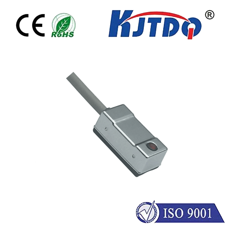
- Power Supply: Ensure the DC voltage (commonly 10-30V DC) matches the sensor’s specifications. Polarity is critical: Connect Brown (or Red) wire to V+, Blue (or Black) wire to 0V (Ground). The Black (or sometimes Blue/Brown stripe) wire is the PNP output signal.
- Load Compatibility: Verify that the device you are connecting the sensor’s output to (PLC input, relay, indicator) is designed to accept a sourcing (PNP) signal. Connecting a PNP sensor to a sourcing PLC input requires an external component (usually a pull-down resistor) and is generally not recommended unless explicitly designed for it.
- Sensing Distance: Be mindful of the sensor’s rated nominal sensing distance (Sn). Performance decreases as the target approaches the limit. Factors like target material (steel vs. non-ferrous), size, and shape affect the effective range. Never mount the sensor flush if its specification requires a non-flush mounting distance.
- Environment: Choose sensors with appropriate ingress protection (IP ratings) for damp, dusty, or washdown environments. Consider temperature ranges and potential chemical exposure.
- Inductive Targets: Remember, standard inductive PNP sensors detect metallic objects. For non-metallic targets (plastic, wood, liquid), capacitive, ultrasonic, or photoelectric sensors are necessary.
The PNP proximity sensor, with its sourcing output characteristic, offers a robust, reliable, and often logically intuitive method for non-contact object detection. Its inherent compatibility with common sinking PLC inputs simplifies system integration. While the choice between PNP and NPN depends heavily on regional practices and the specific