analog inductive proximity sensor
- time:2025-09-07 00:58:50
- Click:0
The Unsung Hero of Precision Detection: Unveiling the Power of Analog Inductive Proximity Sensors
In the intricate dance of modern automation, where machines move with millimetric precision and processes demand unwavering consistency, a silent sentinel often plays a pivotal role: the analog inductive proximity sensor. Far from being just an “on/off” switch, this robust workhorse offers a continuous stream of valuable data, making it indispensable for applications demanding nuance beyond simple presence detection. But what exactly makes this analog variant so powerful?
Beyond Binary: The Essence of Analog Inductive Sensing
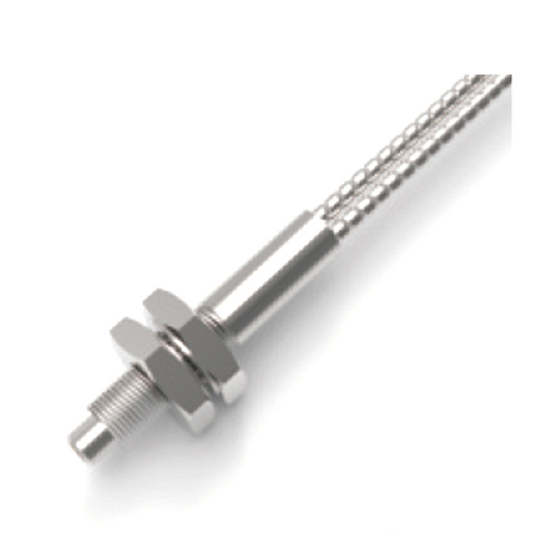
At its core, an inductive proximity sensor operates on fundamental electromagnetic principles. It generates a high-frequency oscillating electromagnetic field using a coil wound around a ferrite core within its sensing face. When a metallic target enters this field, it disrupts it, inducing small electrical currents called eddy currents within the target material. These eddy currents, in turn, draw energy from the sensor’s coil, causing a measurable change in the oscillation’s amplitude.
Here’s where the critical distinction lies. A digital inductive sensor interprets this change simplistically: once the disturbance crosses a fixed threshold, it triggers a discrete “target present” signal (usually switching an output transistor). It’s binary – on or off.
An analog inductive proximity sensor, however, takes a deeper dive. Instead of just triggering a switch, it continuously measures the degree of change in the oscillating circuit, typically the amplitude dampening. This measurement is then converted into a proportional, continuously variable electrical output signal.

The Output Language: Continuous Data Streams
This continuous output is the superpower of the analog sensor. It typically manifests in two common formats:
- Voltage Output (e.g., 0-10V DC, 1-5V DC): The output voltage varies proportionally with the distance between the sensor face and the target. For example, at the rated sensing range (Sn), the output might be 10V; as the target moves closer, the voltage decreases linearly towards 0V (or vice versa, depending on configuration).
- Current Output (e.g., 4-20mA): Widely favored in industrial environments for its superior noise immunity over long cable runs, the output current changes proportionally with the target distance. A common standard is 4mA representing “no target in range” and 20mA representing “target at nominal sensing distance.”
Why Choose Analog? The Compelling Advantages
The ability to provide a distance-proportional signal unlocks a wealth of applications impossible for simple digital switches:
- Precision Position Monitoring: Track the exact position of moving metal parts, like hydraulic/pneumatic cylinder rods, valve stems, or slides. This enables precise control and feedback within complex machinery.
- Vibration Analysis & Runout Detection: Measure tiny variations in the distance of a rotating shaft or vibrating component. Analog sensors excel at detecting eccentricities, imbalances, or bearing wear before catastrophic failure occurs, enabling predictive maintenance.
- Non-Contact Thickness Measurement: Monitor the thickness of metal strips, sheets, or coatings by precisely gauging the distance to the material surface on both sides or relative to a known reference.
- Differentiation by Material: Certain advanced analog sensors can be tuned to respond differently to various metals (like ferrous vs. non-ferrous), allowing for material identification tasks alongside proximity sensing.
- Optimizing Process Parameters: Continuously monitor the position of metal parts within a process to dynamically adjust speed, pressure, or feed rates for optimal efficiency and quality.
- Eliminating Mechanical Wear: As a non-contact sensing solution, they avoid the wear and tear associated with mechanical limit switches, significantly extending operational life and reducing maintenance downtime.
Key Characteristics Defining Performance
Understanding these specifications is crucial for selecting the right sensor:
- Sensing Range (Sn): The theoretical maximum distance at which the sensor can detect a standard mild steel target. Crucially, the analog output is only linear over a portion of this range (e.g., 0-Sn). Always consult the datasheet for the linear operating range.
- Linearity: A measure of how accurately the output signal (voltage or current) corresponds to the actual target distance across the specified operating range. Lower linearity error means higher precision. High linearity is paramount for accurate position measurement.
- Hysteresis: The difference in the switching point when the target approaches versus when it recedes. While present, it’s a secondary concern compared to linearity for most analog applications focused on the continuous signal value.
- Frequency Response: How quickly the sensor’s output can track rapid changes in target distance. This is vital for high-speed or vibration-sensing applications.
- Temperature Drift: The degree to which the output signal is affected by ambient temperature changes. Good sensors have specifications defining this drift to ensure stable readings across operating conditions.
- Shielding: Shielded sensors have their electromagnetic field concentrated towards the front, making them suitable for tight installations. Non-shielded types have a larger lateral field but may detect metal objects to the side if not carefully mounted.
Navigating the Selection Process: Key Considerations
Choosing the optimal analog inductive sensor requires careful evaluation:
- Required Range and Precision: Define the minimum and maximum distances you need to measure and the required accuracy (linearity).
- Target Material: Mild steel provides the longest range. Stainless steel reduces it significantly; non-ferrous metals (aluminum, copper, brass) reduce it even further. Factor this into range calculations.
- Operating Environment: Consider temperature extremes, potential exposure to coolants, oils, cutting fluids, or welding splatter. Choose a housing material (stainless steel often preferred) and ingress protection (IP) rating (e.g., IP67, IP69K) accordingly.
- Output Signal Type: Decide between voltage (0-10V, 1-5V) or current (4-20mA), considering noise immunity needs and PLC/controller compatibility.
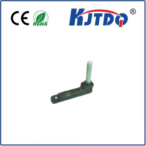
- Mounting Constraints: Space limitations dictate sensor size and shape (barrel, rectangular block). Determine if a shielded or non-shielded model is needed.
- Response Time and Frequency: Ensure the sensor is fast enough to track the expected movement speed or vibration frequency of your target.
The Indispensable Tool for Intelligent Automation
While their digital counterparts excel at simple presence detection, analog inductive proximity sensors offer a sophisticated layer of intelligence to automated systems. By delivering a continuous, distance-proportional output signal, they transform mere detection into valuable quantitative feedback. Whether it’s ensuring micron-level precision in manufacturing, safeguarding machinery through vibration monitoring, or enabling dynamic process control, the nuanced information provided by these sensors is foundational to achieving higher levels of efficiency, quality, and reliability. Their robust, non-contact nature further solidifies their position as a versatile and enduring solution in the demanding landscape of industrial automation.