check

check

check

check
check

check
check
check
check
check
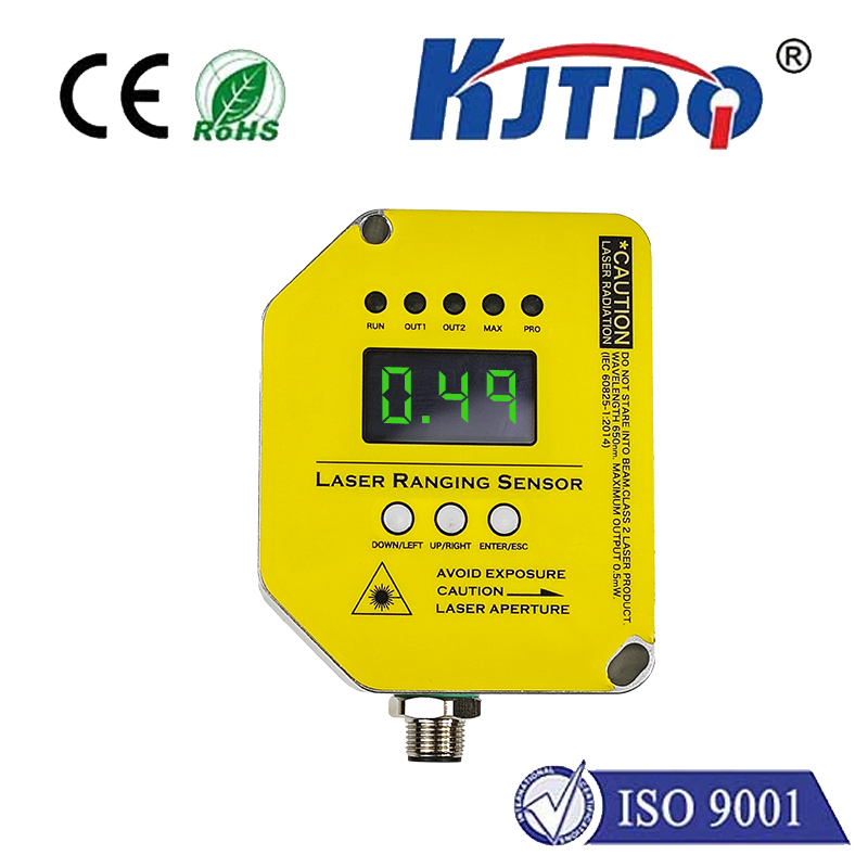
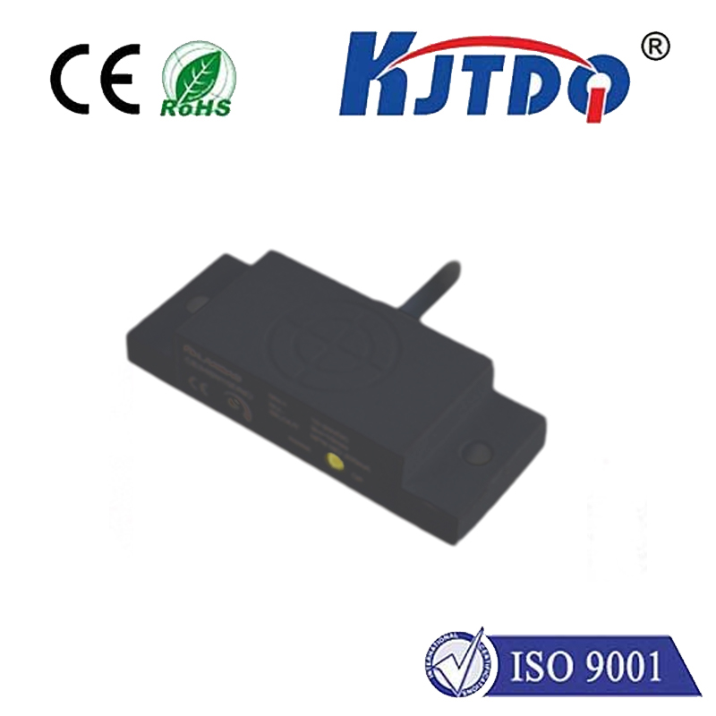
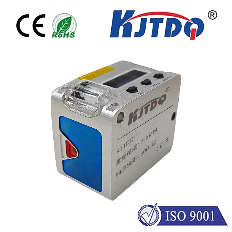
Imagine an invisible dance of light, silently measuring distances, triggering actions, or preventing collisions within the intricate machinery of our automated world. That’s the essence of the infrared proximity sensor, a ubiquitous workhorse in industrial automation, robotics, and countless electronic devices. But within this category, a specific variation stands out for its unique electrical behavior: the PNP infrared proximity sensor. Understanding its operation is crucial for designing robust and reliable detection systems.
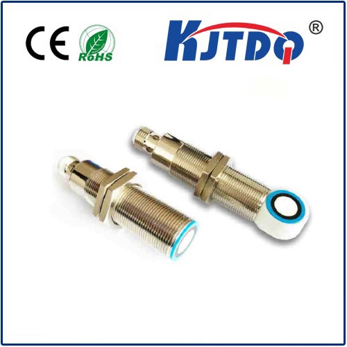
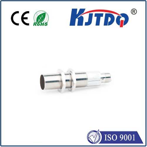
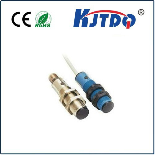
At its core, an infrared proximity sensor functions by emitting infrared (IR) light and sensing its reflection off a nearby object. Think of it as an invisible echolocation system using light instead of sound. An internal IR LED emits pulses of infrared radiation. If an object enters the sensor’s detection range, some of this IR light reflects back towards the sensor. A dedicated photodetector (like a phototransistor or photodiode) picks up this reflected signal. The sensor’s electronics then process this signal, comparing its strength to a threshold. When the reflected signal surpasses this threshold – indicating an object is sufficiently close – the sensor triggers its output switch.
Here’s where the critical distinction between “PNP” and its counterpart “NPN” comes into sharp focus. These terms refer to the type of transistor used in the sensor’s output stage and define the electrical behavior of the output signal relative to the common ground (0V). This distinction dictates how the sensor integrates into your circuit.
The Heart of the Matter: PNP Output Operation
A PNP infrared proximity sensor is fundamentally a sourcing sensor. When its output is active (meaning an object is detected), the sensor provides a positive voltage (typically the supply voltage, +V) to the connected load. Think of it as connecting the load to the positive supply rail.

Visualizing the Current Flow (Active State):
+Vs (Supply Voltage, e.g., +12V or +24V)
|
|
|-------> [PNP Sensor Output] -----> (Connects to LOAD Input +)
|
|
|
LOAD (e.g., PLC Input, Relay, Controller)
|
|
|
V
GND (0V)
Key Characteristics of PNP Sensors:
Why Choose a PNP Infrared Proximity Sensor?
The suitability of PNP versus NPN depends heavily on the input requirements of the device you’re connecting the sensor to (e.g., PLC input module, microcontroller, relay module). Here’s where PNP shines:
Typical Applications:
PNP IR proximity sensors find robust application wherever reliable, contactless detection is needed, especially in environments favoring sourcing signals:
PNP vs. NPN: A Crucial Distinction
Understanding the difference is non-negotiable for correct system integration. Here’s a quick comparison:
| Feature | PNP Infrared Sensor | NPN Infrared Sensor |
|---|---|---|
| Output Type | Sourcing | Sinking |
| Active State | Provides +V to Load | Provides GND (0V) path for Load |
| Inactive State | Output High-Impedance (Open) | Output High-Impedance (Open) |
| Current Flow (Active) | From Sensor Output -> INTO Load -> to GND | From +V -> Through LOAD -> INTO Sensor Output -> to Sensor GND |
| PLC Input Compatibility | Sinking Inputs (Common +) | Sourcing Inputs (Common -) |
| Logic Level (Active) | High (+V) | Low (0V) |
Integrating a PNP Sensor: Key Considerations
The PNP infrared proximity sensor is a fundamental component in modern automation, prized for its robust sourcing output that integrates intuitively with common control system architectures like PLCs using sinking inputs. *