hydraulic proximity sensor
- time:2025-09-06 03:31:30
- Click:0
Hydraulic Proximity Sensors: The Ultimate Guide to Reliable Position Detection in Fluid Power Systems
Imagine a massive excavator arm smoothly lifting tonnes of earth, or a high-speed stamping press performing flawlessly thousands of times a day. Now picture the catastrophic consequences if a critical component moved unpredictably – a hydraulic cylinder extending too far, a piston slamming beyond its intended stroke. Preventing such scenarios is the silent, vital role of the hydraulic proximity sensor. These specialized devices are the unsung heroes ensuring precision, safety, and efficiency in demanding fluid power applications, acting as the digital eyes that keep hydraulic systems under control.
Understanding the Core Technology
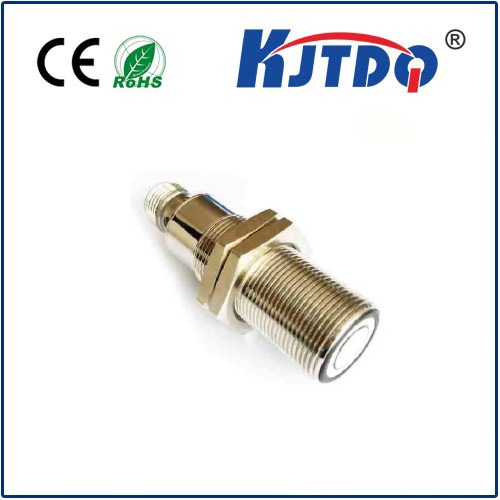
At its heart, a hydraulic proximity sensor is an electronic device designed specifically to detect the presence or absence of ferrous metal (like steel or iron) components within hydraulic systems without any physical contact. They are typically mounted externally on the body of a hydraulic cylinder or internally within hydraulic manifolds and valve blocks. Their primary function is to monitor the position of pistons, rods, spools, or other moving parts within the harsh environment of pressurized hydraulic fluid.

The vast majority operate on the inductive sensing principle:
- Generating the Field: An internal oscillator circuit generates a high-frequency alternating electromagnetic field radiating from the sensor’s active face.
- Detection Trigger: When a ferrous metal target (like a piston rod or a specific point on a hydraulic spool) moves proximity to this field, electromagnetic induction occurs.
- Field Disturbance: The approaching target causes eddy currents to form within the metal. These currents absorb energy from the sensor’s electromagnetic field.
- Signal Shift: This energy absorption alters the amplitude or frequency (depending on sensor design) of the oscillator circuit.
- Output Switching: An internal evaluation circuit detects this change and triggers a solid-state electronic switch. This switch changes the state of the sensor’s output signal – typically switching from OFF to ON (or vice versa) when the target reaches the predefined sensing distance (switching point).
Why Hydraulic Proximity Sensors Are Indispensable
Traditional mechanical limit switches struggle in the punishing world of hydraulics. Hydraulic proximity sensors offer distinct, crucial advantages:
- Non-Contact Operation: This is paramount. No physical contact means no wear and tear from moving parts, eliminating mechanical failure points like levers or rollers. This translates directly to vastly longer service life and reduced maintenance costs.
- Extreme Environment Resilience: They are engineered to thrive where mechanical switches fail:
- High Pressure: Sealed designs withstand the intense pressures found inside cylinders and manifolds without leaking or failing.
- Temperature Extremes: Constructed from materials stable across typical hydraulic fluid operating temperature ranges, and often beyond.
- Vibration & Shock: Solid-state construction makes them highly resistant to the shocks and vibrations endemic to heavy machinery.
- Contamination Resistance: While the sensing face needs to be kept relatively clean, the elimination of moving parts makes them inherently more resistant to dust, dirt, and oil ingress than mechanical alternatives.
- High Switching Frequencies & Speed: Capable of detecting rapidly moving targets, making them suitable for high-cycle applications where mechanical switches would quickly fatigue.
- Precise & Repeatable Sensing: Offers consistent and accurate switching at a specific, predefined distance from the target, critical for precise position control.
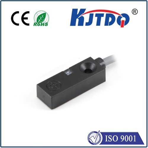
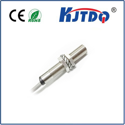
- Sealed & Compact Designs: Available in robust, space-efficient housings (like M8, M12, M18, M30 threaded barrels) designed for direct hydraulic mounting, simplifying installation in tight spaces.
Critical Applications Across Industry
Hydraulic proximity sensors are ubiquitous wherever precise, reliable position feedback is needed in fluid power systems:
- Cylinder End-Position Detection: The most common use. Accurately signalling when a hydraulic cylinder piston has reached its fully extended or fully retracted position. This is vital for cycle control, sequencing, and preventing cylinders from over-stroking and damaging themselves or machinery.
- Multi-Position Control: Multiple sensors along a cylinder barrel can detect intermediate piston positions, enabling complex sequencing without needing full-stroke travel.
- Valve Spool Position Feedback: Monitoring the position of spools inside directional control valves to confirm commanded shifts have occurred or to provide feedback for closed-loop control systems.
- Travel Monitoring: Tracking the movement of hydraulic components within presses, injection molding machines, material handling equipment, and construction machinery.
- Clamping Verification: Confirming that hydraulic clamps or chucks have securely engaged a workpiece before a machine cycle begins.
- Leak Detection (Indirect): While not a direct leak sensor, unexpected position signals can sometimes indicate pressure loss preventing a component from reaching its destination, prompting further investigation.
Selecting the Right Hydraulic Proximity Sensor
Choosing the optimal sensor requires careful consideration of the application’s specifics:
- Sensing Distance: The critical distance at which the sensor reliably detects the target. Must account for mounting tolerances and potential target movement. Never select one that operates at its absolute maximum range in practice. A safety margin is essential.
- Target Material & Size: Primarily designed for ferrous metals. Detection distance can vary slightly based on the specific metal alloy. Ensure the target size is sufficient for reliable detection at the chosen sensing distance.
- Housing Material & Type: Must withstand hydraulic fluid chemistry (oil type), pressure, and environmental contaminants (water, coolants, cleaning agents). Common materials include nickel-plated brass and robust stainless steel (e.g., 303, 304). The physical size and thread (M8, M12, M18, M30) must fit the mounting location.
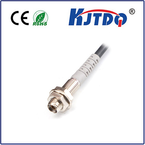
- Electrical Output & Connection: Available as Normally Open (NO), Normally Closed (NC), or changeover contacts. Output types: AC, DC (2-wire, 3-wire NPN/PNP). Voltage ratings must match the control system. Choose the appropriate plug connector or cable outlet.
- Pressure Rating (IP Rating): Critical for sensors mounted inside pressurized zones. Ensure the sensor’s specified pressure rating exceeds the maximum system pressure. For external mounting, a high IP rating (like IP67, IP68, IP69K) is essential to protect against water, dust, and high-pressure washdowns, common in hydraulic environments.
- Temperature Range: Must operate reliably within the expected ambient and hydraulic fluid temperature range of the application.
- Electrical Protection: Look for features like reverse polarity protection, short-circuit protection, and surge protection to enhance durability in electrically noisy industrial environments.
- **Output