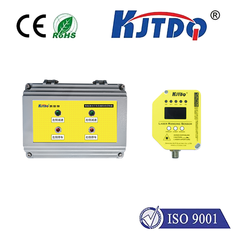
optical position sensor working principle
- time:2025-08-15 00:17:18
- Click:0
Unveiling the Magic: How Optical Position Sensors Pinpoint with Precision
Title: Illuminating Movement: The Core Working Principles of Optical Position Sensors
Introduction: Where Light Meets Location
In a world increasingly driven by automation, robotics, and precise measurement, knowing the exact position of an object is paramount. Imagine a robot arm seamlessly assembling a phone, a drone maintaining stable flight, or a high-precision CNC machine carving intricate patterns. At the heart of many of these feats lies a technology as brilliant as it is fundamental: the optical position sensor. Unlike contact-based sensors prone to wear, optical sensors harness light to detect movement and position without physical touch, offering unparalleled accuracy, speed, and reliability. But how do these remarkable devices translate beams of light into precise positional data? Let’s illuminate the core working principle of these ubiquitous sensors.
The Fundamental Idea: Light as the Measurement Tool
The core principle of an optical position sensor hinges on detecting changes in light properties caused by the movement or position of a target object. Instead of mechanical probes, these sensors utilize:

- A Light Source: Typically a Light Emitting Diode (LED) or laser diode generates the initial light beam. LEDs are common for diffuse reflection and proximity sensing, while lasers offer focused beams ideal for long-range or high-resolution applications.
- A Photodetector (or Array): This is a light-sensitive component, such as a photodiode, phototransistor, or, crucially, a specialized device like a Position Sensitive Detector (PSD) or a Charge-Coupled Device (CCD)/Complementary Metal-Oxide-Semiconductor (CMOS) image sensor. Its job is to convert incoming light photons into an electrical signal.
- The Target: The object whose position needs to be measured. The target might reflect light (like a white mark on a rotating shaft), block light (like a gear tooth), or inherently modulate light (like an optical encoder disc).
The sensor’s intelligence lies in interpreting how the interaction between the emitted light and the target alters the light pattern reaching the photodetector. This change directly correlates to the target’s position.
Key Working Methods
Several distinct working principles are employed, each suited to different applications:
- Triangulation (Reflective Sensing): This is a common principle for distance or displacement measurement over relatively short ranges.
- A focused light beam (often laser) strikes the target surface.
- The beam reflects off the target at an angle.
- The reflected beam lands onto a Position Sensitive Detector (PSD) or a linear photodiode array.
- Crucially: If the target moves closer to the sensor, the reflection spot moves one way across the detector. If the target moves farther away, the spot moves in the opposite direction.
- The PSD or array outputs electrical signals proportional to the centroid (center point) of the light spot illuminating it. By analyzing these currents or pixel outputs, the sensor’s electronics precisely calculate the target’s position relative to the sensor. This method excels at non-contact distance measurement.
- Object Blocking/Transmission (Slotted Opto-Interrupters): This principle detects the presence or passage of an object.
- The sensor houses an LED on one side and a photodetector (like a phototransistor) directly opposite.
- When no object interrupts the light path, the light beam hits the photodetector, which conducts current.
- When an opaque object passes through the slot between them, it blocks the light path. The photodetector ceases conducting (or conducts significantly less).
- The change in the detector’s output signal indicates the object’s presence or passage. While primarily a proximity/object detection sensor, the timing and sequence of these signals in systems (like rotary or linear encoders) can translate directly into position information relative to known reference points. This forms the basis of simple incremental position sensing.
- Optical Encoding (Incremental & Absolute Encoders): This is perhaps the most widespread application of optical position sensors for precise angular or linear position and velocity feedback, especially in motors and machinery.
- The Disc/Scale: A rotating disc (for rotary) or linear scale features a precisely patterned track. For incremental encoders, this is typically alternating opaque and transparent lines. Absolute encoders have complex, unique patterns representing each position with a unique digital code (often using Gray code).
- Light Source & Detectors: An LED illuminates the disc/scale pattern. On the opposite side (for transmission) or the same side (for reflection), one or more photodetectors or photodiode arrays are aligned to detect the light/dark pattern.
- How Position is Determined:
- Incremental Encoding: As the disc rotates or the scale moves, the alternating pattern causes the detector(s) to generate pulse trains (often called A and B quadrature channels). The number of pulses counts incremental movements. The phase relationship between A and B signals determines the direction of movement. A single pulse per revolution (Z-channel) provides a zero reference point. Position is derived by counting pulses relative to the index. Resolution is high, but position on power-up requires homing.
- Absolute Encoding: The complex pattern on the disc/scale creates a unique combination of light/dark conditions across multiple detector tracks simultaneously. This unique pattern corresponds to a unique digital binary or Gray code output. This directly indicates the absolute position within one revolution or stroke upon power-up, without needing movement or a reference point. Resolution depends on the number of tracks (bits).
Why Optical? Advantages of Light-Based Sensing
The optical position sensor principle offers compelling advantages over mechanical or magnetic counterparts:
- Non-Contact Measurement: Eliminates friction, wear, and slippage, ensuring long-term reliability and accuracy.
- High Precision & Resolution: Capable of detecting movements down to nanometers or arc-seconds with the right design (especially encoders and laser triangulators).
- High Speed Response: Light travels fast, enabling measurements at very high speeds, critical for dynamic systems.
- Immunity to Magnetic Fields: Unaffected by magnetic interference, making them ideal for harsh industrial environments where motors or magnets are present.
- Versatility: Can measure angular position (rotary encoders), linear displacement (linear encoders, laser triangulation), proximity (slot sensors), and fine distance changes.
Bringing Precision to Life: Real-World Applications
The optical position sensor working principle is the silent workhorse enabling precision across countless fields:
- Industrial Automation: Servo motors (position feedback), CNC machines (tool position), robotic arms (joint angles), pick-and-place systems.
- Consumer Electronics: Computer mice, trackpads, optical zoom mechanisms in cameras, autofocus systems, gaming controllers, printers/scanners.
- Medical Devices: Surgical robots, imaging systems, infusion pumps, diagnostic equipment.
- Automotive: Throttle position, suspension height, steering angle sensors (increasingly optical for autonomy).
- Aerospace & Defense: Flight control surfaces, antenna positioning, inertial navigation aids.
- Scientific Instrumentation: Microscopes (stage position), telescopes, spectrometers.
Conclusion: A Light-Powered Future of Precision
From the fundamental interaction of light with a surface in triangulation, to the precise decoding of patterned light in encoders, the optical position sensor working principle elegantly transforms photons into actionable positional data. By leveraging light’s speed, precision, and non-contact nature, these sensors provide


