optical displacement sensor working principle
- time:2025-08-14 16:51:25
- Click:0
How Optical Displacement Sensors Work: Light-Based Precision Measurement Demystified
Imagine needing to measure the position or tiny movement of an object – a component on a high-speed assembly line, the vibration of a turbine blade spinning at thousands of RPM, or the microscopic thickness of a silicon wafer. Traditional contact methods like dial gauges are often too slow, intrusive, or simply impossible. Enter the optical displacement sensor, a marvel of modern engineering that uses the fundamental properties of light to perform precise, non-contact measurement with remarkable speed and accuracy. This technology underpins countless applications, from factory automation and robotics to scientific research and quality control. But how exactly does light translate into a distance reading? The core working principle revolves around analyzing changes in light reflected from a target.
The Foundation: Light as the Measuring Stick
At its heart, an optical displacement sensor operates on the principle of non-contact measurement. It projects a beam of light, typically a focused spot or a line, onto the target surface whose position or displacement needs to be measured. Crucially, the sensor doesn’t physically touch the target. Instead, it meticulously analyzes characteristics of the reflected light beam. Changes in the target’s position alter how this light returns to the sensor. The specific way the sensor detects and interprets these changes defines the primary methods: laser triangulation, confocal imaging, and interferometry.
Laser Triangulation: Geometry in Action

This is arguably the most common working principle for optical displacement sensors, especially in industrial settings, prized for its balance of precision, speed, range, and cost-effectiveness. Here’s the step-by-step process:
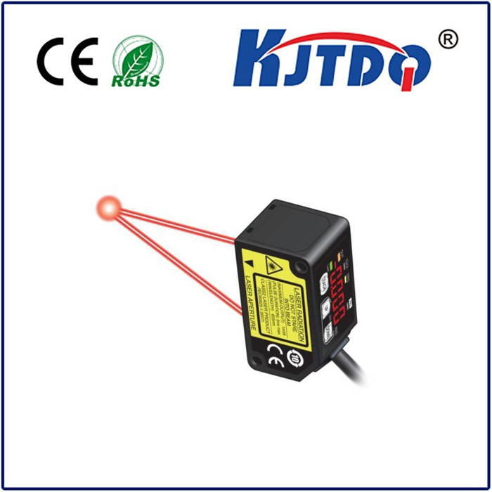
- Light Emission: A laser diode emits a highly focused, collimated beam of light (often red or blue laser) directed precisely onto the target surface.
- Reflection & Scatter: The target surface reflects and scatters this incident light. The specific reflection pattern depends on the surface properties (e.g., shiny metal vs. rough plastic).
- Receiving Optics: The scattered light travels back towards the sensor. A precisely positioned lens (receiver lens), located at a known angle relative to the laser emitter, collects a portion of this reflected light.
- Spot Position Detection: The collected light is focused onto a position-sensitive detector (PSD). The PSD isn’t just a simple on/off detector; it’s typically a linear array of photodiodes (like a tiny one-dimensional camera) or a specialized analog device that outputs an electrical signal corresponding to the exact centroid or position of the light spot falling on it.
- The Crucial Geometric Link - Triangulation: This is where the principle gets its name. The sensor, the point where the laser hits the target, and the spot position on the PSD form a triangle. When the target moves closer or farther from the sensor:
- A target moving closer causes the reflected beam to hit the receiving lens at a steeper angle. This focuses the spot onto a different position on the PSD.
- A target moving farther away causes the reflected beam to hit the receiving lens at a shallower angle, shifting the focused spot to a different location on the PSD.
- Signal Processing & Output: The sensor’s built-in electronics continuously monitor the electrical signal from the PSD. Sophisticated algorithms precisely calculate the displacement of the light spot centroid on the detector. Using calibrated geometric relationships (the fixed angles and distances within the sensor itself), this spot displacement is converted directly into a highly accurate measurement of the target’s distance or change in position relative to the sensor. This distance data is then output digitally or as an analog voltage/current signal for use by control systems or data loggers.
Variations: Coaxial Triangulation addresses limitations with steep angles or holes by aligning the emission and reception paths through the same optical axis using beam splitters, minimizing shadowing effects. Auto-Focus Systems move the receiver lens to keep the spot focused, extending usable range at the expense of speed.
Confocal Principle: Pinpoint Axial Resolution
Confocal chromatric sensors use a different working principle to achieve exceptional axial resolution (resolution along the beam axis), often in the nanometer or sub-micron range, ideal for transparent layers or highly reflective surfaces.
- Broadband Light Source: A white light or multi-wavelength LED emits light.
- Chromatic Lens: The light passes through a special lens designed to refract different wavelengths (colors) by different amounts. This means each specific wavelength focuses at a different, precise distance along the optical axis.
- Reflection and Spectral Discrimination: The light hits the target. Only the wavelength that is perfectly in focus at the exact target distance will reflect back optimally and pass efficiently through a small pinhole aperture placed in front of the detector. Light from wavelengths focused above or below the target is largely blocked by the pinhole.
- Spectrometer Analysis: The spectral composition of the light passing through the pinhole is analyzed by a spectrometer. The peak intensity wavelength detected corresponds directly to the distance of the target surface from the sensor. Displacement is measured by tracking shifts in this peak wavelength.
Interferometry: Harnessing Light Waves
Optical interferometers represent the pinnacle of precision for displacement measurement, capable of resolutions down to picometers (trillionths of a meter), primarily used in metrology labs and high-end manufacturing like semiconductor lithography.
- Laser Beam Splitting: A highly stable, coherent laser beam (e.g., HeNe) is split into two paths: a reference beam and a measurement beam.
- Path Travel: The measurement beam travels to the target surface and reflects back. The reference beam travels a fixed internal path within the sensor head.
- Interference: The returning measurement beam recombines with the reference beam. Because laser light is coherent (waves are in phase), they interfere with each other. Where peaks align, they constructively interfere (bright fringe); where a peak meets a trough, they destructively interfere (dark fringe).
- Fringe Counting & Phase Analysis: As the target moves, the path length of the measurement beam changes relative to the fixed reference path. This causes the interference pattern (fringes) to shift. By precisely counting the number of bright/dark fringe transitions or analyzing the phase shift between the two recombined beams, the sensor calculates the displacement of the target. Each fringe shift typically corresponds to half the wavelength of the laser light used.
Choosing the Right Optical Principle: Practical Considerations
While the underlying working principle defines the core technology, selecting the right optical displacement sensor involves balancing several factors beyond just distance range:
- Resolution & Accuracy: Interferometry > Confocal > Triangulation (generally, though high-end triangulation rivals confocal).
*


