stepper motor with limit switch
- time:2025-08-08 02:06:07
- Click:0
Stepper Motor with Limit Switch: Precision Positioning with Essential Boundaries
Imagine needing to position something incredibly precisely, like a robotic arm or a microscope stage, but also needing absolute certainty it won’t accidentally slam into its physical boundaries. This fundamental challenge in automation finds a powerful and reliable solution in the combination of a stepper motor and a limit switch. More than just components, their synergy creates a robust system capable of accurate, repeatable motion within defined safe zones. This article delves into why this pairing is indispensable and how it operates.
The Stepper’s Precision, The Switch’s Assurance
At its core, a stepper motor excels in open-loop control. It moves in distinct rotational increments or “steps” in response to electrical pulses. Given the right driver and controller, it achieves remarkable positional accuracy without needing feedback sensors (like encoders) just to move to a commanded position. Its predictability – knowing exactly how many pulses equate to how much rotation – makes it ideal for applications demanding controlled displacement, like 3D printers, CNC machines, automated linear stages, and robotic positioning systems.
However, relying solely on step counting carries inherent risks:
- Lost Steps: If the motor encounters unexpected resistance (a jam, collision, excessive load), it might miss steps. The controller thinks it’s in position A, but physically, it could be miles off at position B.
- Reference Uncertainty: After power-up, how does the system know where “home” is? Without an absolute reference point, precise positioning becomes chaotic.
- Boundary Violation: Blindly trusting step counts risks catastrophic collisions if the motor attempts to move beyond the physical limits of the mechanism.
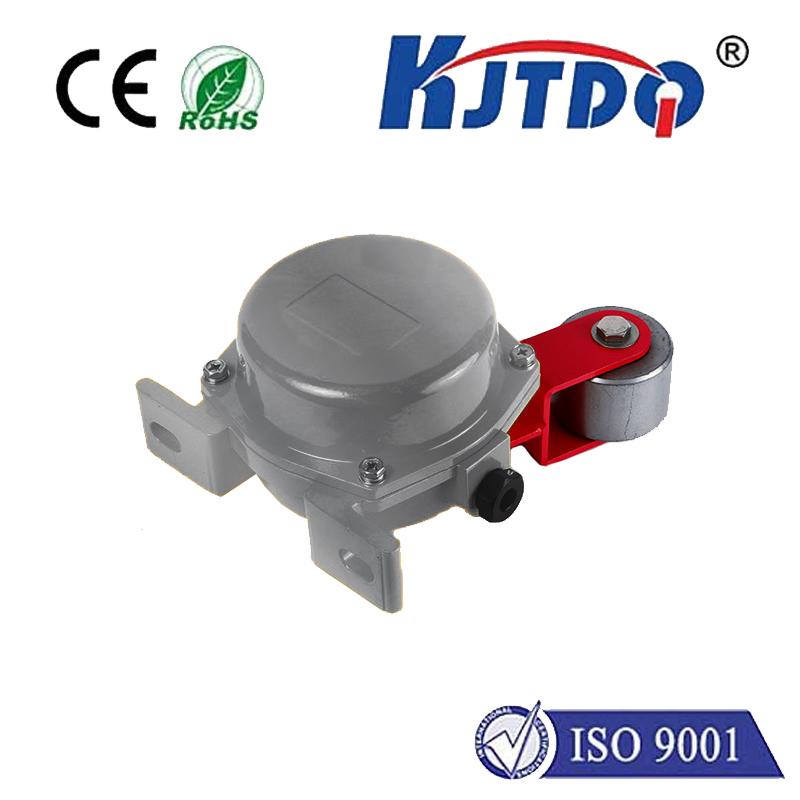
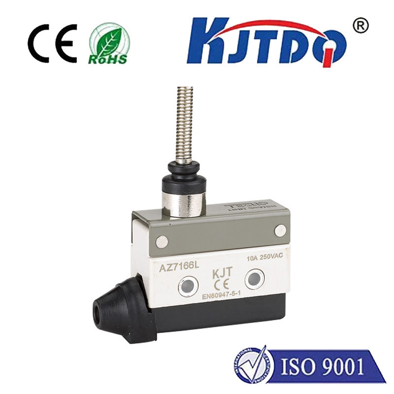
This is where the humble but critical limit switch enters the scene. Physically positioned at the desired endpoints of motion travel (typically the “home” position and one or both extremes), it acts as a definitive, physical sensor. When the moving part of the machine (the carriage, arm, etc.) contacts the switch actuator (lever, roller, plunger), it triggers an electrical signal. This signal acts as an absolute truth for the system controller.

How They Work Together: The Synergy
Integrating limit switches with a stepper motor creates a closed-loop system specifically for boundary detection and homing. Here’s the typical workflow:
- Homing Sequence (Establishing Zero): This is the most critical routine.
- The controller commands the motor to move slowly (often called “jogging”) towards the designated home limit switch.
- Upon contact, the switch is activated, sending a signal to the controller: “Home Position Reached!”.
- The controller instantly stops the motor or may slightly reverse it to “back off” the switch precisely. Crucially, it resets its internal position counter to zero. This establishes the absolute reference point for all future moves.
- The system now “knows” exactly where it is, relative to home.
- Travel Limit Protection:
- Switches are also placed at the maximum desired travel limits (e.g., Max Left, Max Right, Max Up, Max Down).
- During normal operation, if the motor attempts a move that would carry it beyond these physical limits, the corresponding limit switch is triggered before a crash occurs.
- This signal acts as an emergency stop command for the motor driver, halting motion instantly to prevent damage to the mechanism, the motor, or the switch itself. It’s like digital bubble wrap safeguarding your machine.
Key Benefits of the Combination
- Enhanced Reliability & Safety: Prevents destructive crashes against end-stops, protecting valuable equipment.
- Absolute Positioning: Guarantees knowledge of the “home” position after power-up or after a potential lost-step event, restoring system integrity.
- Simplicity & Cost-Effectiveness: Limit switches are relatively inexpensive, robust, and easy to integrate compared to full closed-loop encoders. They provide critical boundary feedback where absolute precision throughout the entire travel might not be necessary.
- Reduced Calibration Complexity: Homing to a physical switch drastically simplifies setup compared to purely software-based positioning systems.
- Improved System Stability: Mitigates the primary weakness of open-loop stepper control (lost steps causing positional drift) by providing a fixed reference point.
Integration Considerations
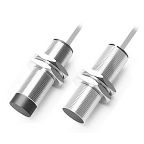
- Switch Type: Choose robust switches suitable for the environment (e.g., sealed switches for dust/moisture). Common types include lever, roller plunger, and proximity switches (though mechanical are most common for homing/limits due to distinct actuation).
- Actuation Force: Ensure the moving part reliably triggers the switch without jamming or excessive force.
- Wiring & Logic: Switches are typically wired as normally open (NO) or normally closed (NC). NC is often preferred for safety-critical limits because a broken wire mimics the switch being triggered, causing a safe shutdown. Careful consideration of switch logic is vital for fail-safe operation.
- Controller/Driver Compatibility: The motor driver or motion controller must have dedicated inputs for limit and home switch signals and be programmed to respond appropriately (stop, reverse, reset position).
Real-World Applications: Where Precision Meets Protection
The stepper + limit switch duo is ubiquitous:
- 3D Printers: Homing the print head and bed to a precise zero point; preventing axes from crashing into gantry ends.
- CNC Routers/Mills: Establishing machine zero; preventing movement beyond the physical table size.
- Automated Linear Actuators/Stages: Defining travel limits; finding repeatable start positions for tests or processes.
- Robotic Arms (Basic): Setting known starting joint angles; preventing over-rotation that could damage wiring or joints.
- Conveyor Positioning Systems: Stopping pallets or carriers at exact loading/unloading stations; preventing runaway movement.
- Automated Test Equipment: Precisely positioning probes or devices under test; ensuring mechanisms don’t collide with fixtures.
Beyond the Basics: Evolution
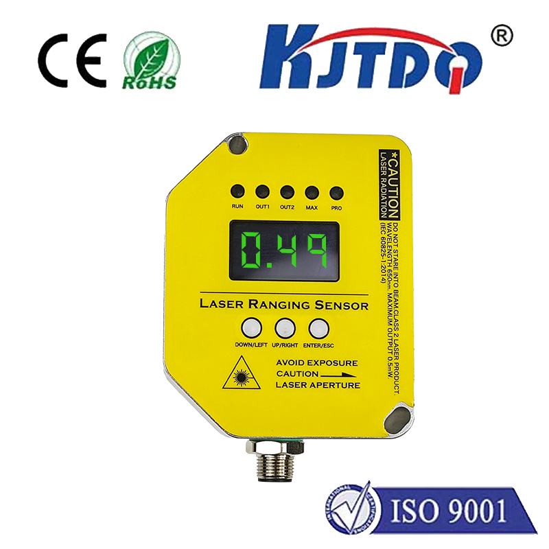
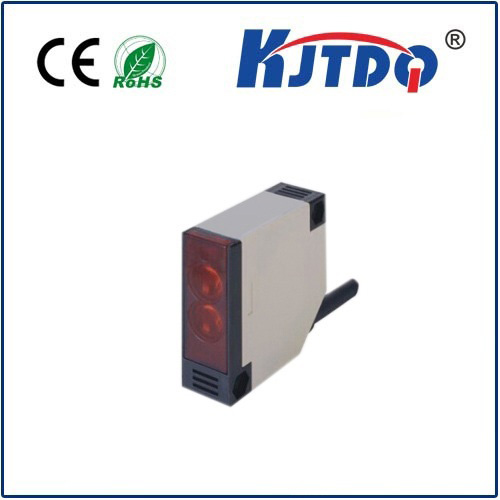
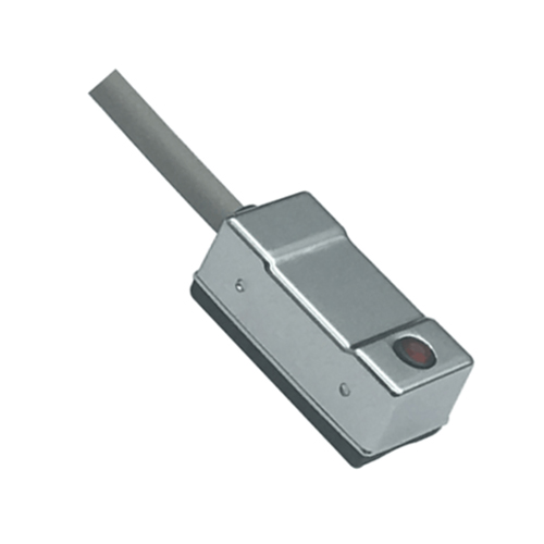
While traditional mechanical limit switches are the mainstay, technology evolves. Optical sensors or Hall effect sensors offer contactless limit detection. Proximity sensors can detect metal flags without physical touch. However, the fundamental principle remains: providing an absolute, physical reference to define boundaries and establish home.
Conclusion
The pairing of a stepper motor and limit switch is a cornerstone of reliable and safe automation. It leverages the stepper’s inherent step precision while mitigating its key vulnerability through the absolute positional feedback provided by physical switches. This combination delivers robust, cost-effective positioning within defined boundaries, making it an essential design pattern for countless applications demanding controlled movement without the risk of overtravel or the uncertainty of an unknown starting point. Mastering this integration is fundamental for engineers and hobbyists building dependable motion control systems.


