worm drive limit switch
- time:2025-08-08 01:40:54
- Click:0
Worm Drive Limit Switches: The Robust Guardians of Precision Positioning
Imagine a massive industrial gate humming along its track, a powerful conveyor belt transporting heavy materials, or a critical hydraulic ram extending with force. Now picture the potential disaster if any of these mechanisms moved beyond their intended stopping point. Over-travel isn’t just an inconvenience; it causes catastrophic equipment damage, costly production downtime, and severe safety hazards. This is where the unassuming yet crucial worm drive limit switch steps in, acting as a reliable mechanical sentinel to enforce safe and precise operational boundaries. Combining the inherent strength of a worm gear with the essential function of a limit switch, this component is a cornerstone in heavy-duty motion control systems.
Understanding the Core: Worm Gears Meet Electrical Switching
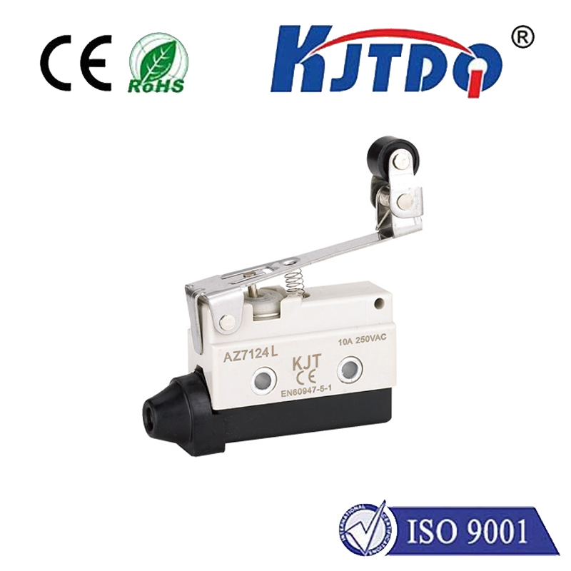
Fundamentally, a limit switch is an electromechanical device designed to detect the presence or position of an object. It typically consists of an actuator (a lever, roller, or plunger) physically moved by the target machinery. This movement triggers internal electrical contacts to open or close, sending a signal to a control system – essentially telling the machinery to stop, start, reverse, or initiate another programmed sequence.
The key differentiator of the worm drive limit switch lies in its actuating mechanism. Instead of relying on a simple cam or direct lever action, it incorporates a worm gear assembly. Here’s the breakdown:
- The Worm: A threaded shaft (like a screw) that rotates.
- The Worm Wheel (Gear): A specially designed gear with curved teeth that mesh perfectly with the worm thread.
When the lever arm attached to the worm shaft is moved (often by a cam or striker attached to the moving machinery), the worm rotates. Due to the unique meshing of worm and wheel, this rotation translates into a very precise, controlled movement of the worm wheel. This wheel, in turn, drives the internal mechanism that operates the electrical contacts. This gearing provides significant mechanical advantage.

Why Choose Worm Drive? Key Advantages
This seemingly simple gear arrangement bestows several critical benefits, making worm drive limit switches the preferred choice for demanding applications:
- High Mechanical Advantage & Torque Capacity: The worm gear design provides substantial mechanical leverage. This means a relatively small force applied to the lever arm (by the moving mechanism) generates a much larger force within the switch to operate the contacts reliably, even against stiff springs or dirty environments. They handle high shock and vibration effortlessly.
- Precise Adjustment & Repeatability: Worm drives allow for very fine positioning. Adjusting the point at which the switch triggers can be achieved accurately by rotating the worm shaft slightly. Once set, the inherent characteristics of the worm gear ensure highly repeatable operation cycle after cycle, crucial for consistent machine performance and safety.
- Self-Locking Capability: A fundamental property of most worm gear configurations is self-locking. When not actively being driven, the friction between the worm and wheel prevents the wheel from back-driving the worm. In practical terms, this means:
- The switch position won’t drift unintentionally due to vibration.
- If the moving machinery stalls or loses power after tripping the switch, the contacts remain securely in their triggered state, maintaining the safety signal. This positive mechanical override is vital for fail-safe operation.
- Overload Protection: The robust construction and inherent strength of the worm gear assembly act as a built-in overload clutch. If the lever arm is subjected to excessive force beyond its design limits (e.g., a severe jam or impact), the worm gear may slip internally rather than breaking the lever arm or internal components. This protects the critical switching elements and allows for easier reset after the overload condition is cleared.
- Durability in Harsh Environments: Typically constructed from heavy-duty materials like cast iron housings and hardened steel gears, these switches are built to withstand punishing industrial conditions – dust, dirt, moisture, temperature extremes, and corrosive elements. They often feature high IP (Ingress Protection) ratings (e.g., IP65, IP67) signifying resistance to dust and water jets.
Key Components & Design Variations
While robust, a worm drive limit switch isn’t simplistic:
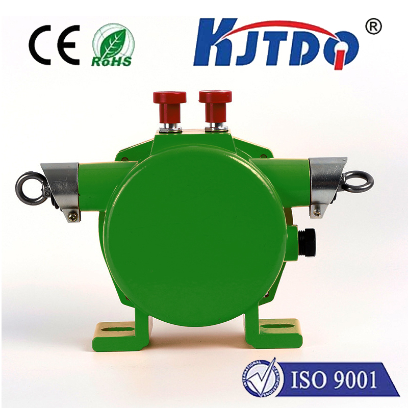
- Housing: Provides protection and mounting. Cast iron is common for maximum toughness; aluminum alloys offer corrosion resistance and lighter weight where applicable.
- Worm Gear Assembly: The heart of the switch, comprising the worm shaft and worm wheel gear.
- Actuator Lever: The external arm that interfaces with the machine’s moving part (cam, striker plate). Lever styles vary significantly (straight, fork, roller) to suit different application needs.
- Electrical Contacts: The switching element itself. Common configurations include Single-Pole Single-Throw (SPST - NO or NC), Single-Pole Double-Throw (SPDT), and Double-Pole Double-Throw (DPDT). Materials like silver alloy ensure reliable conductivity and long life.
- Terminals: Connection points for wiring (screw terminals, plug connectors).
- Seals & Gaskets: Essential for achieving the required IP rating and protecting internal components.
- Position Indicators: Visual cues showing the switch state (actuated/non-actuated).
Where Worm Drive Limit Switches Excel: Applications
The unique strengths of worm drive limit switches make them indispensable in industries and machinery requiring robust position detection and safety interlocks:
- Material Handling: Gates, hoists, cranes, stackers/reclaimers, conveyor systems (end-of-travel, position verification).
- Construction Equipment: Excavator booms, crane jibs, hydraulic cylinder end-of-stroke control.
- Hydraulic & Pneumatic Systems: Cylinder stroke limit detection for presses, lifts, and actuators.
- Heavy Machinery: Position control in rolling mills, large valves, and process equipment.
- Power Generation: Dams, sluice gates, turbine control mechanisms.
- Mining & Quarrying: Crushers, screens, feeder positioning in extremely harsh environments.
Selecting the Right Switch: Critical Considerations
Choosing the optimal worm drive limit switch involves evaluating several factors:
- Operating Environment: Temperature range, presence of dust, moisture, chemicals, oil, explosive atmospheres (requiring specific certifications like ATEX/IECEx).
- Mechanical Load: Anticipated force and frequency of impact on the lever arm. Select adequate torque capacity.
- Electrical Requirements: Voltage, current (AC/DC), contact configuration (NO/NC/Changeover), electrical rating of contacts.
- Duty Cycle: How often will the switch be actuated? Continuous operation vs. intermittent use.
- Required Accuracy & Repeatability: Precision needed for the stopping point.
- Mounting & Actuator Style: Physical space constraints and the type of cam or striker interacting with the switch.
- Certifications & Ratings: Mandatory safety standards (ISO 13849, IEC 60947-5-1), IP rating, material certifications.
In the relentless world of industrial automation and machinery, precision and safety are non-negotiable. The worm drive limit switch, with its robust worm gear mechanism and unwavering reliability, stands as a critical line of defense. Its mechanical advantage, self-locking capability, **over


