upper and lower limit switch crane
- time:2025-08-08 01:05:40
- Click:0
The Essential Guide to Crane Limit Switches: Preventing Over-Travel for Optimal Safety
Imagine the sudden jolt, the grinding screech, and the terrifying seconds as a crane’s hook block collides violently with its upper structure, or crashes down onto the cab below. Such catastrophic events, often resulting in severe equipment damage, costly downtime, and unthinkable safety hazards, are precisely what upper and lower limit switches are designed to prevent. These indispensable safety sentinels silently govern the vertical travel of cranes, acting as the final line of defense against dangerous over-travel scenarios. Understanding their function, types, and critical importance is paramount for any operation relying on overhead lifting equipment.
Understanding the Core Function: Defining the Travel Limits
At its simplest, a crane limit switch is an electromechanical device strategically positioned to detect when a moving part of the crane (typically the hoist hook block or trolley) reaches a predefined point at the extreme ends of its allowable vertical path. They establish vital safety boundaries:
- Upper Limit Switch: Positioned near the top of the crane’s lift path. Its sole purpose is to stop the hoisting motion upwards before the hook block or load makes contact with the crane’s structure (like the bridge girder, trolley frame, or drum). This prevents crushing damage to components and potential structural overload.
- Lower Limit Switch: Positioned near the absolute lowest point the hook block should travel. Its function is to halt the lowering motion downwards before the hook block or load crashes onto the floor, a pit, the cab, or personnel below. This protects the load, surrounding infrastructure, and most critically, people.
How They Work: The Tripping Mechanism

While sophisticated electronic variants exist, the most common crane limit switches operate on a reliable physical principle:
- Activation Arm/Lever: A protruding arm or lever is mounted on a fixed part of the crane structure at the precise upper and lower travel limits.
- Striker Plate: A corresponding plate or cam is attached to the moving component (e.g., the hoist rope block).
- Contact: As the block ascends or descends, the striker plate physically contacts the activation arm of the limit switch.
- Circuit Interruption: This physical contact forces the switch mechanism to open or close its electrical contacts. This action instantly cuts power to the hoist motor’s control circuit, stopping the hoisting or lowering motion in that specific direction.
- Safety Reset: Crucially, limit switches are designed so that the hoist can typically only be operated away from the tripped limit. For example, if the upper limit triggers, the hoist can usually only be lowered; it cannot be raised again until the block descends sufficiently to reset the switch. This prevents immediate re-activation towards the hazard.
Key Types of Limit Switches Used in Cranes
Several designs cater to different crane configurations and robustness requirements:
- Rotary Cam Limit Switches: Feature rotating cams that actuate internal micro-switches at precise angular positions. Commonly used for trolley and bridge travel limits, but also configured for hoist limits with lever arms. Offer good precision and multiple switching points.
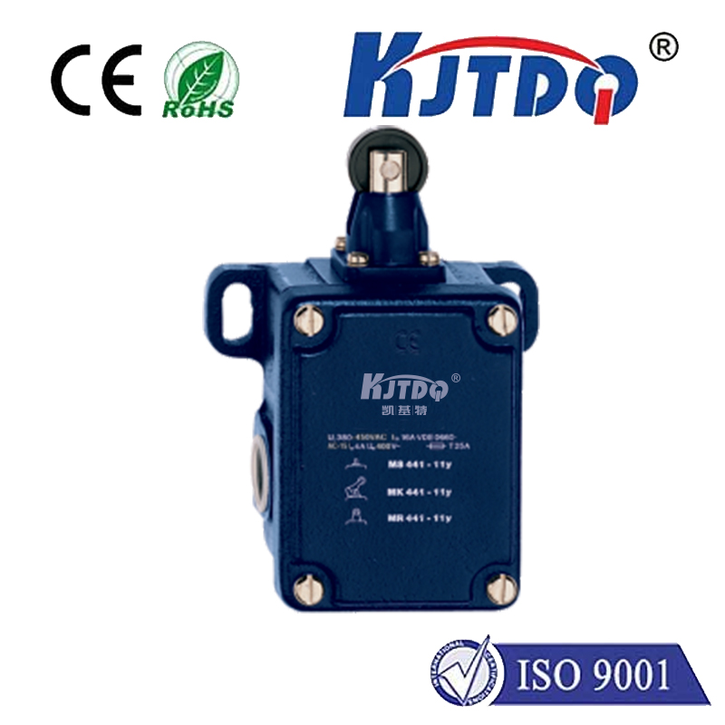
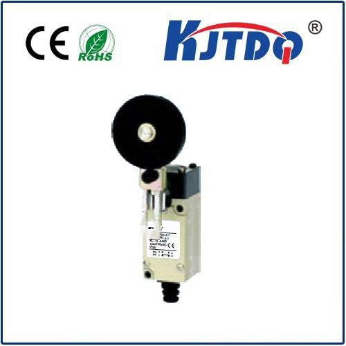
- Lever Arm Limit Switches: A very common type for hoist limits. A physical lever arm is deflected by the striker plate, actuating the switch contacts inside. Simple, robust, and reliable.
- Weight Limit Switches (for Lower Limit): Often used as the final, failsafe lower limit. A weight suspended by the hook block triggers the switch if the block descends too far, providing redundancy beyond the primary lever switch. This is sometimes called a “deadman” limit.
- Rod Type Limit Switches: Utilize a plunger or rod that is physically depressed to actuate the switch. Suitable for precise positioning points.
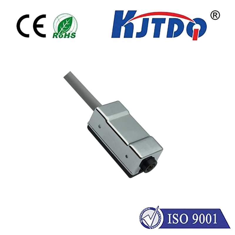
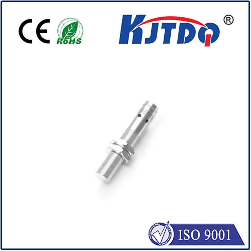
- Magnetic/Proximity Switches: Non-contact switches that detect the presence of a metal target. Less prone to mechanical wear but require careful calibration and shielding from electrical interference. Often used as secondary limit switches or for warning zones.
Why Limit Switches are Non-Negotiable for Crane Safety
The role of upper and lower limit switches extends far beyond mere convenience; they are fundamental to safe crane operation:
- Preventing Catastrophic Collisions: This is the primary function. They stop the hook block from smashing into vital crane structures above or crushing objects/people below.
- Protecting Crane Integrity: Collisions cause immense stress on beams, motors, drums, ropes, and sheaves. Limit switches prevent this damage, extending equipment lifespan and reducing costly repairs.
- Avoiding Cable Overload & Failures: Allowing a hook block to over-hoist can cause the hoist rope to “two-block” (hook contacts load block), potentially spooling off the drum or snapping under massive tension. Limit switches prevent this.
- Mitigating Load Swing and Instability: Sudden stops upon collision can cause dangerous load pendulum effects. Controlled stops initiated by limit switches are inherently safer.
- Critical Redundancy in Safety Systems: They act as the final mechanical/electrical backup to operator control and any programmable warning systems.
- Compliance with Regulations: Adherence to stringent safety codes and standards (like OSHA, ANSI/ASME B30.2, ISO) mandates the presence and proper functioning of operational limit switches on powered cranes. Failure to comply risks penalties and liability.
Essential Maintenance and Testing Vigilance
Like any safety-critical component, limit switches demand regular attention:
- Scheduled Inspections: Integrate limit switch checks into the routine preventive maintenance schedule. Look for physical damage, corrosion, loose mounting hardware, damaged wiring, and obstructions around the activation arm and striker plate.
- Functional Testing: This is non-negotiable. Operators should test limit switches daily as part of their pre-shift inspection:
- Slowly hoist the unloaded hook block towards the upper limit until the switch trips and stops motion.
- Slowly lower the hook block towards the lower limit until the switch trips and stops motion.
- Verify power is cut and the hoist can only move away from the tripped limit.
- Resist Tampering: Switches must never be bypassed, blocked, or adjusted to allow travel beyond the designed safe limits. This is extremely hazardous and illegal.
- Timely Replacement: If a switch fails a test, shows damage, or malfunctions, operations must cease immediately. The crane must be tagged out of service until a qualified technician repairs or replaces the faulty switch.
Beyond the Basics: The Crucial Link in the Safety Chain
Upper and lower limit switches are neither glamorous nor complex, but they represent a cornerstone of industrial safety. They embody the critical engineering principle of designing safeguards that function independently of human vigilance. While operator training and awareness are vital, limit switches provide that essential, automated fail-safe, physically preventing dangerous over-travel. Investing in their proper selection, installation, maintenance, and rigorous testing isn’t just about protecting equipment; it’s about safeguarding personnel, preventing devastating accidents, and ensuring responsible, compliant crane operations. Never underestimate the power of these seemingly simple devices to avert disaster.


