pneumatic controls limit switch - KJT
搜索

pneumatic controls limit switch

  • time:2025-08-06 12:38:51
  • Click:0

Pneumatic Controls Limit Switch: The Essential Sentinel for Air Cylinder Position

Imagine this: A precisely controlled robotic arm executing repetitive motions on an assembly line. Suddenly, it overshoots its intended stopping point. The result? Damaged product, costly downtime, or even a safety hazard. What failed? Often, it’s the unsung hero – or more accurately, the critical sentry – known as the pneumatic controls limit switch. This small but vital component ensures air-powered systems operate safely, reliably, and within their designed parameters by detecting the endpoint positions of pneumatic actuators like cylinders and rotary actuators.

Understanding the Core Function: Position Verification in Air Systems

Pneumatic systems use compressed air to generate motion and force through components like air cylinders. While the direction and flow of air are managed by valves, knowing exactly when a cylinder rod has fully extended or retracted is paramount for precise machine sequencing and safety. This is precisely where the pneumatic limit switch steps in.

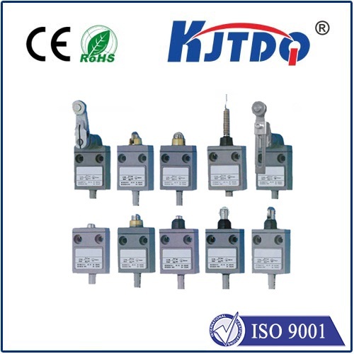
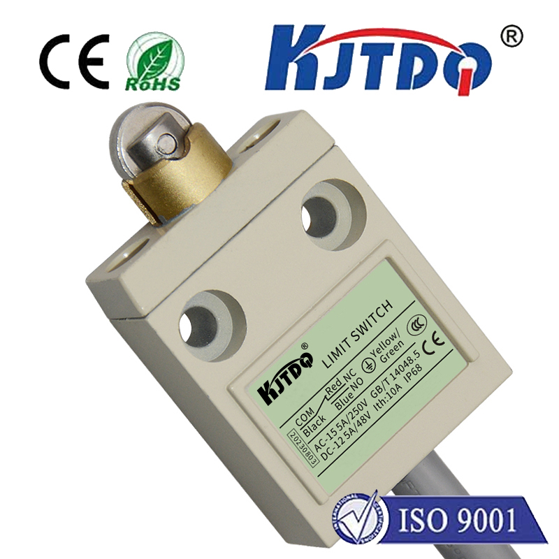
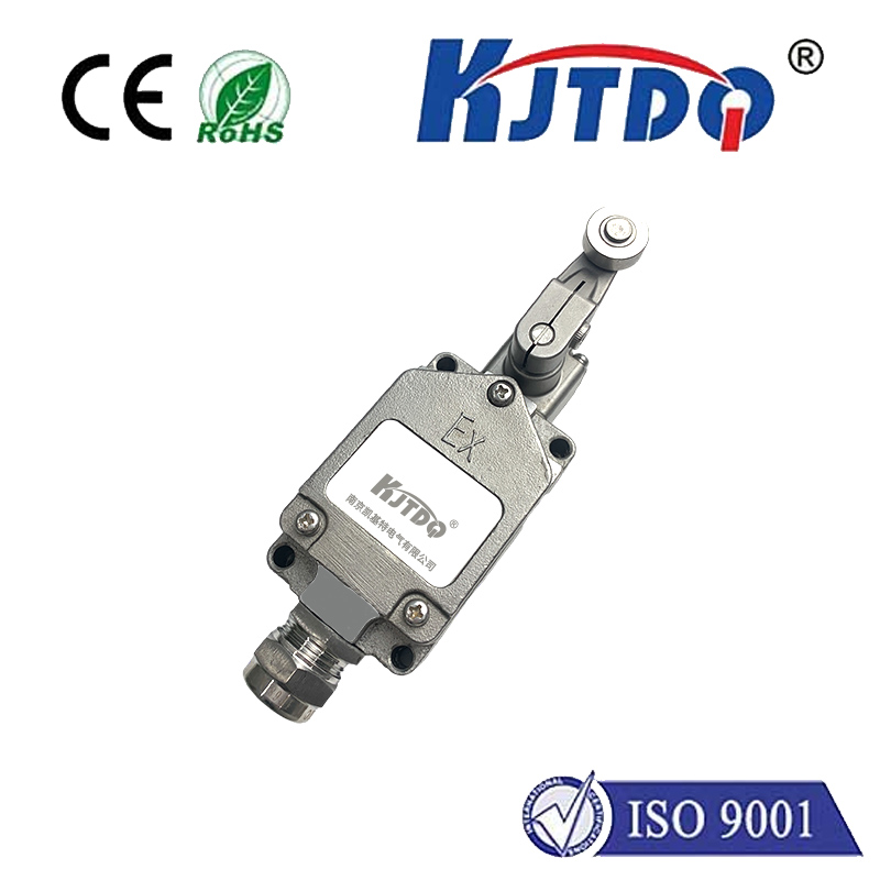
Essentially, a pneumatic controls limit switch is an electromechanical device strategically mounted along the path of a pneumatic actuator. It incorporates an actuator mechanism (lever, roller plunger, push rod, etc.) designed to be physically contacted by the moving part of the cylinder (like the rod or a target mounted on it) when it reaches a specific position. This physical contact triggers an internal switch mechanism.

The Critical Switch Mechanism & Output Signal

The heart of the limit switch is its internal switching element. When the actuator is engaged by the cylinder’s movement, it changes the state of this switch – typically opening or closing an electrical circuit. This change generates a definitive electrical signal (NO - Normally Open, or NC - Normally Closed). This signal is the fundamental output.

This switch output signal serves as critical feedback for the pneumatic control system (often a PLC - Programmable Logic Controller):

  1. Position Confirmation: “Cylinder A has fully extended.” “Cylinder B has fully retracted.”
  2. Sequencing Control: The PLC uses this signal to initiate the next step in the machine cycle (e.g., activating another cylinder, starting a timer, turning on a tool).
  3. Safety Interlocks: Preventing the next potentially hazardous action from occurring until the cylinder is confirmed to be in the safe “home” position. Think guarding or preventing collisions.
  4. Fault Detection: If the expected signal doesn’t arrive at the PLC within a programmed time window, it indicates a potential malfunction (jammed cylinder, broken rod, switch failure), triggering an alarm or shutdown.

Key Characteristics Defining Pneumatic Limit Switches

While the core function is straightforward, several features define a switch’s suitability for demanding pneumatic environments:

  • Robust Construction: These switches face constant mechanical impact, vibration, dust, moisture, and potential exposure to cutting fluids or washdowns. Sturdy housing materials (metal or high-grade plastic) and high IP (Ingress Protection) ratings (e.g., IP65, IP67) are essential for durability and reliability. NEMA ratings (like NEMA 4X, 13) are also common indicators of environmental protection.
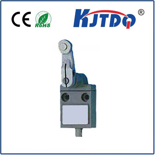
  • Actuator Type: The physical interface matters. Roller lever actuators are common for cam or rod contact. Plunger-type actuators suit direct push applications. Rotary lever actuators might be used for specific mounting angles. The choice depends on the cylinder’s motion profile and available mounting space.
  • Electrical Ratings: The switch must handle the voltage (commonly 12-24V DC or 120V AC) and current (often < 5A, but varies) required by the control system it feeds. Higher inductive loads (like solenoid valves) might require gold-plated contacts or specific ratings.
  • Repeat Accuracy: Consistent triggering at the same point is vital for precision. High-quality switches offer excellent repeatability.
  • Operating Force & Travel: The force needed to activate the switch and the distance the actuator travels before switching must align with the cylinder’s characteristics to ensure reliable operation without damage. Low operating force options exist for delicate applications.
  • Mounting Versatility: Flexible mounting options – brackets, adjustable arms, clamps – simplify installation and adjustment to precisely align with the cylinder’s stroke endpoints.

Why Pneumatic Limit Switches Remain Indispensable

In an era of sophisticated sensors, why are these mechanical switches still so prevalent in pneumatic controls?

  • Simplicity & Reliability: Their electromechanical nature is inherently straightforward, often making them more robust and less susceptible to certain types of interference than complex electronic sensors in harsh factory environments.
  • Cost-Effectiveness: They typically offer a lower initial cost compared to many proximity sensors or other position feedback technologies.
  • Definitive State: They provide a clear, high-integrity switch signal (on/off), perfect for digital control systems like PLCs needing discrete position confirmation.
  • Ease of Installation & Adjustment: Physical mounting and alignment are generally intuitive for technicians familiar with mechanical systems.
  • Durability: When appropriately specified for the environment, they withstand significant physical abuse.

Selecting and Implementing Pneumatic Controls Limit Switches

Choosing the right limit switch requires careful consideration:

  1. Environmental Conditions: Assess dust, moisture, chemicals, temperature extremes, and washdown requirements to determine the necessary IP or NEMA rating.
  2. Required Actuator Style: Match the actuator type (roller lever, plunger, etc.) to the cylinder’s movement and how it will make contact. Consider side or end-of-stroke mounting.
  3. Electrical Compatibility: Ensure voltage, current ratings, and contact configuration (NO/NC) match the control circuit. SPDT (Single Pole Double Throw) contacts offer flexibility.
  4. Mechanical Load: Account for the speed and force of the cylinder rod/actuator contact to avoid premature switch failure. Check the maximum operating force rating.
  5. Mounting & Adjustment: Ensure the selected switch and any included mounting hardware fit the available space and allow for precise positioning.

Proper installation and adjustment are critical for reliable operation. The switch must be securely mounted so its actuator is positively engaged by the cylinder rod or target at the desired endpoint, without being over-traveled (causing damage) or under-traveled (failing to actuate). Regular inspection for physical damage, loose mountings, and proper operation is part of good preventative maintenance.

The Unseen Guardian of Pneumatic Precision

The pneumatic controls limit switch operates quietly and reliably, often unnoticed until it fails. Yet, its role is fundamental. By providing that crucial electrical confirmation of an air cylinder’s position, it enables automated sequencing, ensures operational safety, prevents damage to machinery and product, and contributes significantly to overall system reliability and efficiency. From simple machinery to complex automation cells, these robust electromechanical sentinels remain a cornerstone of effective pneumatic control, proving that sometimes, a simple switch truly makes all the difference.
Recommended products