plunger limit switch
- time:2025-08-02 01:20:45
- Click:0
Plunger Limit Switches: The Unsung Heroes of Precision Position Detection
Imagine a critical machine component hurtling towards its travel endpoint. Without a vigilant sentinel, catastrophic collision, damage, or even injury could result. Enter the plunger limit switch, a robust and fundamental workhorse in industrial automation. Far more than a simple “on/off” device, this mechanical marvel is a cornerstone of safety, precision, and reliable control in countless applications, often operating unnoticed until its vital role is truly appreciated.
What Exactly is a Plunger Limit Switch?
At its core, a plunger limit switch is a position-sensing device. It detects the presence or absence of an object, typically by physical contact, and translates that mechanical motion into an electrical signal. The defining feature is its actuator: a spring-loaded plunger that protrudes from the switch body. When an external object presses against this plunger, it depresses, overcoming the spring force. This mechanical movement internally triggers a set of electrical contacts to change state – opening or closing a circuit.
This change in the electrical circuit is the switch’s output signal. It acts as a definitive message to the control system: “The target object has reached this specific point.” Think of it as a highly reliable mechanical messenger confirming a physical position.
The Ingenious Mechanics Inside

The brilliance of the plunger limit switch lies in its straightforward yet effective design:
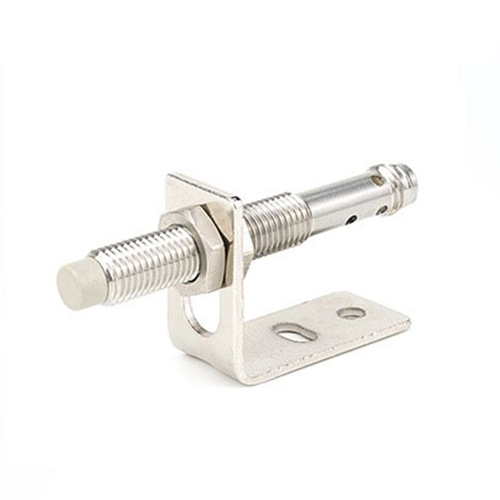
- Plunger Actuator: The visible, movable rod. When force is applied (by a machine part, cam, or object), the plunger moves inward.
- Return Spring: Ensures the plunger snaps back to its original, extended position as soon as the external force is removed. This provides positive reset and repeatability.
- Contact Mechanism: Leveraging a simple but robust switching principle (like Snap-Action), the plunger’s movement directly or indirectly actuates electrical contacts. This is the heart of the signal generation.
- Enclosure: Protects the sensitive internal components from harsh industrial environments – dust, moisture, oil, and physical impact. Robust materials like metal or reinforced thermoplastics are common.
- Electrical Terminals: The connection points for wiring the switch into the control circuit (Common, Normally Open, Normally Closed).
Key Advantages: Why Choose Plunger Limit Switches?
Their enduring popularity stems from several compelling benefits:
- Simplicity & Reliability: Fewer moving parts compared to many electronic sensors mean inherently high reliability and a long operational life when properly applied. Easy to understand and troubleshoot.
- Positive Position Feedback: Provides a definitive, binary (on/off) signal indicating a physical position has been reached. This is crucial for end-of-travel limits, homing sequences, and safety interlocks.
- Mechanical Override Capability: The physical plunger can often be manually depressed for testing or emergency override situations, a feature not always available with non-contact sensors. This can be vital for maintenance and safety checks.
- High Repeatability: Quality plunger limit switches offer excellent positional repeatability, meaning they consistently trigger at very nearly the same point every time the plunger is depressed, essential for precision applications.
- Robustness: Designed to withstand significant mechanical forces, vibration, shock, and challenging environmental conditions prevalent in factories and machinery. They offer excellent resistance to electrical noise (EMI/RFI).
- Cost-Effectiveness: Generally, a highly economical solution for basic position detection needs compared to more complex sensing technologies.
- Fail-Safe Potential: Configurations (like Normally Closed contacts opening on actuation) can be designed as fail-safe, where a broken wire or loss of power inherently signals a fault condition or stops the machine.
Plunger Variations: Tailoring to the Task
Not all plunger actuators are identical. Variations enhance functionality for specific needs:
- Standard Plunger: A simple straight rod; best for direct, head-on actuation.
- Roller Plunger: Features a small rotating wheel at the end. This is ideal for applications where the actuating surface is moving laterally past the switch (e.g., cams, moving platforms), reducing friction and wear for smoother operation and longer life.
- Adjustable Plunger: Allows fine-tuning of the plunger’s pre-travel or operating point.
- Plunger Length & Diameter: Selected based on required reach, operating force, and application space constraints.
Where Do Plunger Limit Switches Shine? Applications Galore
These dependable switches are ubiquitous across industries:
- Machine Tooling: Defining end-of-travel limits on axes (X, Y, Z), confirming tool changer position, safeguarding against over-travel on lathes, mills, and presses. Essential for operator safety.
- Material Handling: Detecting the presence/position of pallets, carts, or products on conveyors; confirming gate or door positions; signaling jam conditions.
- Packaging Machinery: Verifying case erection, flap closure, product presence in filling stations, and labeler positions.
- Robotics: Used as homing sensors to establish a known starting position for robotic arms; setting safe movement boundaries.
- Elevators & Lifts: Providing critical floor leveling signals and confirming door closure status for safety interlocks.
- Industrial Doors: Detecting fully open or fully closed positions of large sectional doors or high-speed doors.
- Valve Position Feedback: Confirming whether a valve is fully open or fully closed.
- Safety Circuits: Integrated into safety gates, guards, and access doors as part of safety interlock systems (often requiring specifically certified safety limit switches like those meeting ISO 13849).
Selecting the Right Plunger Limit Switch: Critical Considerations
Choosing the optimal switch requires careful attention to application specifics:
- Operating Environment: Temperature extremes, presence of moisture (IP rating), dust, oils, chemicals, or washdown requirements. Select an appropriate enclosure material and sealing.
- Electrical Requirements: Voltage and current rating of the load (motor starter coil, PLC input, etc.), AC or DC, type of contacts (SPDT, DPDT). Ensure the switch can reliably handle the connected load.
- Mechanical Specifications: Required operating force (to depress the plunger), plunger travel distance (pre-travel and over-travel), repeatability tolerance, plunger style (standard, roller), and expected lifespan (number of operations). Consider shock and vibration levels.
- Mounting: How and where will the switch be securely mounted? Space constraints?
- Function: Does the application require Normally Open (NO), Normally Closed (NC), or changeover (SPDT) contact action?
- Safety Relevance: If the switch is part of a safety function, it must be a safety-rated component designed and certified (e.g., according to IEC 60947-5-1 Annex K or specific safety standards like ISO 13849) for that purpose. Standard limit switches are NOT safety devices.
Integrating Plunger Switches Effectively
Correct installation is paramount for reliable operation. Key points include:
- Secure Mounting: Use sturdy brackets to prevent movement or misalignment.
- Actuator Alignment: Ensure the actuating mechanism (cam, machine part) cleanly depresses the plunger head-on (for standard plungers) or smoothly rolls onto the roller (for roller plungers). Misalignment causes premature wear.
- Cable Management: Protect wires from snagging, abrasion, and strain using conduit or cable carriers.
- Adjustment & Testing: After installation, verify the switch triggers reliably