proximity sensor no nc
- time:2025-07-16 08:08:16
- Click:0
Proximity Sensors: Decoding NO vs. NC - The Critical Choice for Your Circuit
Understanding the fundamental electrical state of a proximity sensor – whether it’s NO (Normally Open) or NC (Normally Closed) – is not just technical jargon; it’s the cornerstone of designing safe and reliable automated systems. Imagine flipping a switch: does the light come on when you press it, or does it turn off? That basic principle, applied to the invisible world of object detection, defines the operation of proximity sensors and dictates how they interact with your control circuits. Get this choice wrong, and your entire system can malfunction in potentially costly or dangerous ways.
What Exactly is a Proximity Sensor?
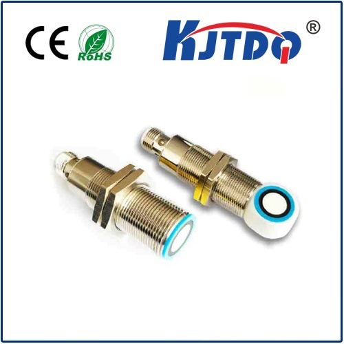
Before diving into NO and NC, let’s briefly recap what a proximity sensor does. These versatile devices detect the presence or absence of a target object without physical contact. They achieve this using various technologies like electromagnetic fields (inductive sensors for metals), infrared beams (photoelectric sensors), ultrasonic waves, or capacitive fields (detecting nearly any material). Their core function is to generate a discrete electrical signal – essentially an “on” or “off” state – based on whether the target is within a specified sensing range.
The Heart of the Matter: Normally Open (NO) vs. Normally Closed (NC)
This is where “NO” and “NC” become crucial. These terms describe the default electrical state of the sensor’s output switch when the sensor is powered on but not detecting the target (i.e., when the target is outside its sensing range). Think of it as the switch’s “resting position.”
- Normally Open (NO):
- Default State (No Target Present): The output switch is open. This means the electrical circuit is broken, and no current flows from the sensor’s output to the connected load (like a PLC input or a relay coil). It’s like a light switch in the “off” position.
- State When Target Detected: When a target enters the sensor’s sensing range, the output switch closes. This completes the circuit, allowing current to flow (“on” signal).
- Mnemonic: Open = Off when no target. Closes On detection.
- Normally Closed (NC):
- Default State (No Target Present): The output switch is closed. The circuit is complete, and current does flow from the sensor’s output (“on” signal).
- State When Target Detected: When a target enters the sensing range, the output switch opens. This breaks the circuit, stopping the current flow (“off” signal).
- Mnemonic: Closed = On when no target. Opens Off on detection.
Why Does NO vs. NC Matter So Much?
Choosing between an NO and NC proximity sensor configuration isn’t arbitrary; it’s dictated by your system’s safety requirements, logic, and failure mode behavior:
- Safety-Critical Applications: This is paramount. Which state is safer if the sensor fails, loses power, or the cable is damaged?
- NC Configuration for Safety: Often preferred in critical situations. Why? If the sensor fails (e.g., wire break, power loss), its output naturally opens (breaks the circuit), signalling a problem or triggering a safe shutdown. For instance, if an NC sensor monitors a safety gate, a broken wire means the gate-open signal is sent, stopping the machine – a fail-safe design. Using an NO sensor here could be dangerous; a broken wire would look like the gate is always closed, even when it’s open.
- NO Configuration: If an NO sensor fails (broken wire, no power), it stays open (off). This might not inherently indicate a problem depending on the logic. It’s crucial to evaluate if this silent failure is acceptable or if additional monitoring is needed.
- System Logic and Control Programming:
- Your PLC or controller logic is written expecting a specific signal behavior. Does your machine need to know when an object is present (use NO for active-high signal) or when an object is absent (use NC for active-high signal when absent)? Mismatching NO/NC requires complex logic inversions within the program, increasing complexity and potential for errors.
Energy Consumption: NC sensors typically consume slightly more power in their default “on” state compared to NO sensors in their default “off” state. While often negligible per sensor, it can be a factor in large-scale deployments with hundreds of sensors.
Circuit Design: Wiring and interface modules might be simplified based on the predominant signal type (active-high vs. active-low) used in your control cabinet.
How Do Proximity Sensors Achieve NO/NC Operation?
Internally, proximity sensors contain solid-state switching elements (like transistors). The sensor’s internal circuitry controls whether these switches are open or closed based on the detection state and the inherent design of the NO or NC version.
- Two-Wire Sensors: These sensors are wired in series with the load (like a PLC input module designed for two-wire sensors). Their internal switching mechanism directly controls the current flow path through the load. An NO two-wire sensor completes the circuit (allows current) when detecting a target. An NC two-wire sensor completes the circuit until a target is detected, then it breaks the circuit.
- Three-Wire Sensors: These have separate power supply wires (typically Brown = +, Blue = -) and a dedicated output wire (typically Black for NPN transistor outputs, White for PNP). The output transistor acts as the switch. The type of transistor (NPN or PNP) combined with whether it’s configured to source or sink current interacts with the NO/NC designation to produce the required signal behavior.
- Four-Wire Sensors: Often provide both an NO and an NC output on separate wires, offering maximum flexibility.
Selecting the Right Proximity Sensor Configuration: NO or NC?
There’s no universal “best” choice. The decision must be made case-by-case:
- Prioritize Safety: Always start here. What happens if the sensor fails? Is it safer for the output to go “off” (open circuit) or stay “on” (closed circuit)? Choose NC for critical stop functions, guard monitoring, or any situation where detecting a loss of signal (failure) is necessary for safety.
- Understand the Desired Signal State: What should the PLC “see”:
- When the target is present?
- When the target is absent?
- If you want a “High” signal (e.g., 24V) when the target is present, you generally need an NO proximity sensor (assuming a PNP/sourcing sensor into a sinking PLC input, or NPN/sinking into a sourcing input).
- If you want a “High” signal when the target is absent, you generally need an NC proximity sensor.
- Evaluate Failure Modes: Beyond safety, consider operational consequences. Is it worse for the machine to stop unnecessarily (potentially caused by an NC false-open) or to keep running when it shouldn’t (potentially caused by an NO failure to close)? NC sensors inherently flag certain failures by losing their signal state.
- Check PLC Input Compatibility: Ensure your control system input cards are configured to correctly interpret the chosen NO vs. NC output behavior, considering voltage levels and sourcing/sinking requirements.
- Consult Standards: Specific industries or machines may have standards dictating preferred practices for NO vs. NC configurations.
Conclusion
The terms “NO” and “NC” on a proximity sensor datasheet are far more than labels; they define the very essence of how the sensor communicates with your control system. Understanding Normally Open


