check

check

check

check
Imagine your garage door opening magically as you approach, or a machine stopping instantly when your hand gets too close. This seamless interaction with the physical world, detecting objects without touch, is powered by proximity sensors. Combining the reliability and affordability of an NPN inductive proximity sensor with the flexibility of Arduino opens a world of automation, safety, and interactive projects. This guide will demystify these components and show you exactly how to make them work together flawlessly. Get ready to add superhuman senses to your next Arduino creation!
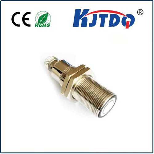
Why Choose NPN Proximity Sensors? Inductive proximity sensors detect metallic objects using an electromagnetic field generated by a coil. Unlike mechanical switches, they wear out slowly because there’s no physical contact. The ‘NPN’ designation refers to the type of transistor output within the sensor. An NPN sensor acts like a low-side switch. When it detects a target, its output signal wire (typically black) connects internally to the sensor’s Negative (0V) wire, pulling the output low (towards 0V). This is crucial for understanding how to connect it to your Arduino board. Think of it as the sensor grounding its output signal when triggered.
The Perfect Pair: Arduino Meets NPN Arduino boards thrive on reading digital signals. An NPN proximity sensor naturally provides this digital LOW signal upon detection, making the integration direct and efficient. Arduino’s input pins are adept at recognizing this change from HIGH to LOW, triggering actions in your sketch. This synergy is what makes NPN proximity sensor Arduino projects so popular and accessible for beginners and experts alike.
Essential Components & Precautions
Wiring: Connecting the Pieces Safely Success hinges on correct wiring. Here’s the standard configuration for an NPN NO (Normally Open) sensor:
setup() function), configure this input pin using pinMode(sensorPin, INPUT_PULLUP);. This uses Arduino’s internal resistor to weakly pull the pin to 5V (HIGH) when the sensor’s output is open (no detection). When the NPN sensor detects an object, it pulls the pin LOW, overriding the weak pull-up. Always double-check your specific sensor’s datasheet regarding the need for an external resistor versus relying solely on the INPUT_PULLUP.Arduino Code: Making Sense of the Signal Here’s a simple Arduino sketch demonstrating how to read an NPN proximity sensor:
// Define the pin connected to the sensor's signal wire (via resistor)
const int sensorPin = 2; // Example pin
void setup() {
// Start serial communication for monitoring (9600 baud)
Serial.begin(9600);
// Configure sensor pin as input WITH internal pull-up resistor
pinMode(sensorPin, INPUT_PULLUP);
}
void loop() {
// Read the state of the sensor pin
int sensorState = digitalRead(sensorPin);
// NPN NO Sensor Logic:
//   When NO object is detected: Signal is OPEN (Pulled HIGH by internal pull-up) -> sensorState = HIGH
//   When Object IS detected: NPN switches ON, pulls signal LOW -> sensorState = LOW
if (sensorState == LOW) {
Serial.println("Object DETECTED!");
// Add your action here (e.g., turn on LED, stop motor, sound alarm)
} else {
Serial.println("No object detected.");
// Add your action here (e.g., turn off LED, start motor)
}
delay(100); // Short delay for readability
}
Key Points in the Code:
pinMode(sensorPin, INPUT_PULLUP);: This activates the internal pull-up resistor on the chosen digital pin, stabilizing it at HIGH when the NPN sensor is inactive (open circuit).digitalRead(sensorPin);: Reads the voltage level on the pin – HIGH (5V) or LOW (~0V).INPUT_PULLUP, the pin is HIGH by default. The NPN sensor pulls it LOW when it detects an object. Therefore, sensorState == LOW indicates detection.Troubleshooting Common Issues
Expanding Your NPN Prouity Sensor Arduino Projects Understanding this fundamental setup unlocks numerous applications: