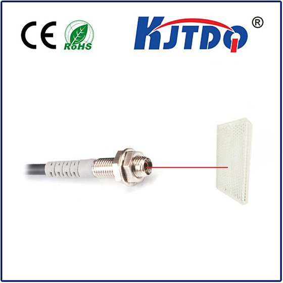
pnp npn proximity sensor
- time:2025-06-20 02:56:29
- Click:0
PNP vs NPN Proximity Sensors: Demystifying Industrial Sensing Outputs
Imagine a bustling factory floor. Robotic arms swing with precision, conveyor belts hum, and sensors silently monitor every movement. Among the most crucial components ensuring this smooth operation are proximity sensors, non-contact sentinels detecting the presence or absence of metal objects. But when ordering replacements or designing a new system, engineers often face a critical choice: PNP or NPN? This seemingly simple question about the sensor’s output wiring holds the key to seamless integration and reliable performance.
At their core, PNP (Positive-Negative-Positive) and NPN (Negative-Positive-Negative) proximity sensors function identically in detecting targets using inductive, capacitive, or magnetic principles. The critical difference lies solely in how they output their signal to the control system – essentially, how they act as an electronic switch to indicate detection.
Understanding the Core Difference: Sourcing vs. Sinking
The fundamental distinction revolves around the direction of current flow when the sensor activates:
- PNP Proximity Sensors (Sourcing Output):
- Function: When activated (target detected), a PNP sensor sources or provides positive voltage (+V, typically 24V DC) to its signal output wire (often brown or black).
- Internal Switch: Think of it as an electronic switch connected between the positive supply voltage (+V) and the output wire. When closed (on detection), it connects the output wire to +V.
- Load Connection: The electrical load (like a PLC input, relay coil, or indicator light) must be connected between the sensor’s output wire and the negative supply terminal (0V). The sensor “sources” the current needed to power the load through to ground.
- Behavior: Output = +V when active (target detected).
- NPN Proximity Sensors (Sinking Output):
- Function: When activated (target detected), an NPN sensor sinks or connects its signal output wire (often black or blue) to the negative supply terminal (0V or ground).
- Internal Switch: Think of it as an electronic switch connected between the output wire and the negative supply (0V). When closed (on detection), it connects the output wire to ground.
- Load Connection: The electrical load must be connected between the positive supply voltage (+V) and the sensor’s output wire. The sensor “sinks” the current flowing from the positive supply, through the load, to ground via its output.
- Behavior: Output = 0V when active (target detected). Note: It is essentially pulling the output line low.
Why Does This Matter? Compatibility is Key.
The crucial implication lies in what the receiving device (like your PLC) expects. PLC digital input modules are typically designed to work with either sourcing (PNP) signals or sinking (NPN) signals.

- Sourcing Input (PLC): This type of PLC input expects the sensor to provide the positive voltage (+V) when active. Therefore, it must be connected to a PNP (Sourcing) Sensor. The PLC input essentially provides the path to ground.
- Sinking Input (PLC): This type of PLC input expects the sensor to connect the input terminal to ground (0V) when active. Therefore, it must be connected to an NPN (Sinking) Sensor. The PLC input essentially provides the connection to +V internally.
Connecting a PNP sensor to a PLC sinking input, or an NPN sensor to a PLC sourcing input, will result in failure to operate. The voltage levels sensed by the PLC will be incorrect for its internal logic.
Regional Preferences and Historical Context
There are often discussions about regional preferences:
- Europe & Asia: Historically, PNP (Sourcing) sensors have been more common. This is often linked to the prevalence of PLCs with sourcing DC inputs in these regions.
- North America: NPN (Sinking) sensors were traditionally more widespread, often associated with older relay logic and initial PLC designs using sinking inputs.
However, this distinction is rapidly blurring. Modern manufacturing facilities are global. PLCs offer modules supporting both types, and engineers readily swap between PNP and NPN sensors based on availability or specific design requirements. The critical factor is always matching the sensor type to the PLC input type, regardless of geography.
Choosing Between PNP and NPN: Practical Considerations
So, how do you decide? Here’s a practical guide:
- Check Your PLC Input Card: This is the most important step. Examine the specifications or labeling of your PLC’s digital input module. It will clearly state whether it requires Sourcing (PNP) or Sinking (NPN) signals. Match your sensor accordingly.
- Wiring Safety & Convenience:
- PNP (Sourcing): Often considered slightly safer in some fault scenarios. If a wire breaks (opens), the signal typically goes inactive (0V). Wiring can sometimes feel more intuitive as the load connects directly between the sensor output and ground.
- NPN (Sinking): If a wire breaks, the signal might inadvertently appear “active” (+V floating) to certain PLCs. Requires connecting the load to +V first.
- Multiple Sensors Sharing a Power Supply: While both can be used, there can be subtle differences in potential ground loop issues depending on the system grounding scheme. Generally, both are viable with proper installation practices.
- Availability & Cost: In many cases, both types are equally available and priced similarly. Choice often comes down simply to compatibility with existing control hardware.
- LED Indicator Behavior: Observe the sensor’s built-in indicator light. Usually:
- PNP: LED ON = Output Active (+V)
- NPN: LED ON = Output Active (0V Connection)
Level Translation: When Worlds Need to Connect
Sometimes, you need to interface sensors of one type to a PLC expecting the other. This requires a signal converter or relay:
- PNP Sensor -> Sinking PLC Input: Use a small relay. Wire the PNP sensor output to switch the relay coil. Connect the PLC input (sinking) between +V and the relay’s normally open (NO) contact. When the sensor is active, the relay pulls in, connecting the PLC input to ground via the NO contact, satisfying the sinking input.
- NPN Sensor -> Sourcing PLC Input: Similarly, use a relay. Wire the NPN sensor output to switch the relay coil. Connect the PLC input (sourcing) between the relay’s NO contact and Ground. When the sensor is active, it sinks the coil current, the relay pulls in, connecting the PLC input to +V via the NO contact, satisfying the sourcing input.
Dedicated solid-state level converter modules are also readily available for a cleaner solution.
Key Takeaways for Reliable Operation
Selecting the right PNP or NPN proximity sensor isn’t about inherent superiority; it’s about system compatibility and understanding electronic fundamentals. Carefully matching the sensor’s output behavior (sourcing or sinking) to your PLC input card


