
check

check

check

check
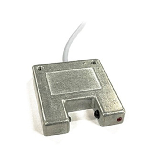
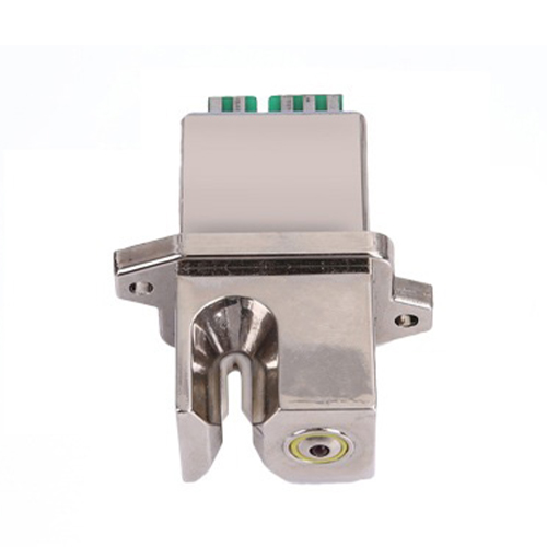
Ever wanted to detect metal objects without physical contact in your Raspberry Pi project, even in dusty or grimy environments? That’s the precise superpower inductive proximity sensors bring to the table. These robust, non-contact detection devices are staples in industrial automation but are equally valuable additions to the Raspberry Pi maker’s toolkit. This guide dives into how inductive proximity sensors work, how to connect them securely to your Raspberry Pi’s GPIO pins, and how to leverage them in your projects for reliable metal detection.
Why Choose Inductive Sensors for Your Pi?
Unlike optical sensors (like infrared break-beams) that struggle with dirt, fog, or varying light conditions, inductive proximity sensors operate on an entirely different principle. They consist of a coil energized by an oscillator. When a metallic object enters the sensor’s electromagnetic field, it induces small currents (eddy currents) within the target metal. This current draw dampens the oscillator’s amplitude. Circuitry monitors this damping effect, triggering a solid-state output signal when a preset threshold is crossed. This non-contact and highly resilient method makes them ideal for:
Understanding the Nuts and Volts: Sensor Outputs
Most industrial inductive proximity sensors come in a 3-wire configuration requiring a DC power supply (typically 10-30V DC). There are two main output types crucial for interfacing with the Raspberry Pi’s 3.3V GPIO:

Here’s the critical point: Raspberry Pi GPIO pins operate at 3.3V logic levels and are NOT tolerant of voltages higher than 3.3V. Connecting a PNP sensor’s output directly to a Pi GPIO when active would apply its supply voltage (e.g., 24V) to the pin, instantly frying it.
Therefore, for safe and reliable operation with Raspberry Pi, we almost exclusively use NPN sensors. When the sensor detects metal, it pulls its signal wire to ground (0V), which is safe for the Pi. We configure the Pi GPIO pin to read this change using an internal or external pull-up resistor.
Bridging the Gap: Wiring an NPN Inductive Sensor to Raspberry Pi
Connecting an NPN sensor involves creating a common ground reference and using a pull-up resistor to define the “high” state. Here’s a breakdown using a common 12V or 24V sensor power supply:
Why the Pull-Up Resistor? When the sensor is inactive (no metal present), its output transistor is OFF (open circuit). Without the pull-up resistor, the GPIO pin would be “floating,” leading to erratic readings. The resistor pulls the GPIO voltage up to 3.3V, giving a clean HIGH signal. When the sensor detects metal, it turns ON, connecting the output (and thus the GPIO pin) strongly to ground (0V), resulting in a LOW reading.
Speaking the Language: Python Code for Detection
With the hardware wired correctly, reading the sensor state in Python is straightforward using libraries like RPi.GPIO or gpiozero. Here’s an example using gpiozero for its simplicity:
from gpiozero import Button  # Button is great for reading digital inputs
from signal import pause
# Replace 17 with your actual GPIO pin number
# The pull_up=True argument uses the Pi's *internal* pull-up resistor.
# IMPORTANT: This *only* works if you DID NOT use an external pull-up resistor as per the wiring above.
# If you used an external resistor, use `pull_up=None` and manage the level in your code.
sensor = Button(17, pull_up=True)  # Sensor acts like a button closing (pulling down) to GND
def metal_detected():
print("Metal Detected!")  # Action on detection (LOW)
def metal_absent():
print("Metal Absent.")   # Action on absence (HIGH)
sensor.when_pressed = metal_detected    # Triggered when pin goes LOW (sensor active)
sensor.when_released = metal_absent     # Triggered when pin goes HIGH (sensor inactive)
pause()  # Keep the program running
Key Considerations for Raspberry Pi Projects:
Unlocking Industrial Potential on a Budget
Integrating inductive proximity sensors with Raspberry Pi opens doors to robust sensing capabilities typically found in expensive industrial controllers. From simple presence detection triggering Pi actions, to building automated counters or rudimentary safety interlocks, the combination offers remarkable flexibility. Whether you’re building a model factory, monitoring equipment, or creating a DIY metal detector setup, understanding **NPN wiring
