inductive proximity sensor for rpm measurement
- time:2025-06-18 02:25:02
- Click:0
Unlocking Precision: Using Inductive Proximity Sensors for Reliable RPM Measurement
Measuring the rotational speed of machinery – its Revolutions Per Minute (RPM) – is fundamental across countless industries. From monitoring engine performance and conveyor belt speeds to ensuring optimal operation of pumps, fans, and turbines, accurate RPM data is crucial for efficiency, safety, and predictive maintenance. While various methods exist, inductive proximity sensors stand out as a remarkably robust and widely adopted solution for this critical task. This article delves into how these versatile sensors work and why they are exceptionally well-suited for precise RPM measurement.
The Heartbeat of Industry: Why RPM Matters
Rotational speed directly impacts machine health, output, and energy consumption. An unexpected drop in RPM might signal bearing failure or impending overload, while an unexpected increase could indicate control system malfunction. Continuous RPM monitoring allows operators to:
- Ensure Process Consistency: Maintain precise speeds for quality control (e.g., mixing, machining).
- Detect Faults Early: Identify issues like shaft misalignment, imbalance, or slipping belts before catastrophic failure.
- Optimize Performance: Fine-tune operations for maximum efficiency and minimal wear.
- Enable Safety Lockouts: Prevent machine starts or operations outside safe speed ranges.
The Inductive Proximity Sensor: A Non-Contact Workhorse
Unlike tachometers requiring physical contact or optical sensors susceptible to dirt and light interference, inductive proximity sensors offer a distinct advantage: non-contact operation. They detect the presence or absence of metallic objects without touching them. This principle is perfectly leveraged for RPM sensing.

How It Works: The Magic of Eddy Currents
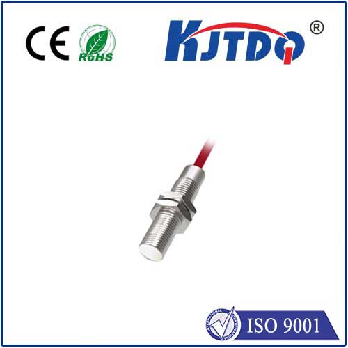
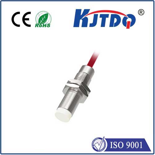
At the core of an inductive proximity sensor lies an oscillator circuit generating a high-frequency electromagnetic field emanating from the sensor’s face. When a ferrous or non-ferrous conductive metal target (like a gear tooth, keyway, bolt head, or a purpose-mounted trigger wheel) enters this field, it induces tiny circulating electrical currents within the target material – called eddy currents. These eddy currents draw energy from the sensor’s oscillating field, causing a measurable change:
- Energy Loss: The eddy currents absorb energy from the sensor’s electromagnetic field.
- Oscillator Damping: This energy loss dampens (reduces the amplitude of) the oscillator’s signal.
- Signal Processing: Internal circuitry within the sensor detects this damping effect.
- Output Switch: When the damping reaches a preset threshold, the sensor triggers its output signal (typically switching from OFF to ON, or vice versa).
Transiting Pulses into Revolutions: The RPM Calculation
For RPM measurement, the sensor is strategically positioned near a rotating component that has regularly spaced metallic features – the ideal target is often a gear or a dedicated slotted disc. As each tooth or slot passes the sensor face:
- Pulse Generation: The sensor detects each approaching metallic feature, generating a distinct output pulse (one pulse per tooth/slot passage).
- Pulse Counting: These pulses are fed into a measuring device – often a Programmable Logic Controller (PLC), frequency counter, tachometer module, or dedicated RPM meter.
- Timing is Key: The measuring device counts the number of pulses received over a precisely defined time interval (e.g., one second, ten seconds). The shorter the interval, the faster the update rate, but potentially with more noise; longer intervals offer smoother readings.
- The Simple Math: RPM is calculated based on the pulse count and the known geometry:
RPM = (Pulses Counted / Time Period in Minutes) / Number of Teeth (or Targets) per Revolution
Time Period in Minutes = (Timing Interval in Seconds) / 60- Example: If you count 120 pulses in 1 second, using a 12-tooth gear:
- Time Period in Minutes = 1 / 60 ≈ 0.01667 minutes
- RPM = (120 / 0.01667) / 12 = (7200) / 12 = 600 RPM
Why Inductive Proximity Sensors Excel at RPM Measurement
Several key attributes make inductive sensors a top choice:
- Non-Contact Operation: Eliminates wear and tear on both sensor and target, ensuring long service life. No friction means no degradation of accuracy over time.
- Robustness: Highly resistant to dust, dirt, oil, grease, and moisture – common challenges in industrial environments where RPM monitoring is critical. This ruggedness is a major advantage over optical sensors.
- High-Speed Capability: Modern inductive sensors can reliably detect very high rotational speeds, generating crisp pulses even for machinery operating at thousands of RPM.
- Solid-State Reliability: No moving parts contribute to their inherent durability and minimal maintenance requirements.
- Simple Installation & Setup: Mounting near a suitable metallic target is typically straightforward. Configuration usually involves setting up the counting/timing parameters on the receiving device.
- Cost-Effectiveness: They offer an excellent balance of performance, reliability, and affordability for industrial sensing tasks.
Key Considerations for Implementation
To ensure optimal RPM measurement results:
- Target Material: Must be a detectable metal (steel, aluminum, brass, copper). Non-conductive materials (plastic, wood) or poorly conductive metals like stainless steel (depending on grade) significantly reduce sensing range and signal strength. Choose targets carefully.
- Target Size & Shape: The sensor must be capable of reliably detecting each feature. General rule: target size should be at least equal to or larger than the sensor’s active face diameter. Avoid irregular shapes that might cause inconsistent detection.
- Sensing Distance: Mount the sensor consistently within its specified nominal sensing range (
Sn) for the target material. Too close risks collision; too far reduces signal reliability. Account for potential target runout or axial movement.
- Pulse Count Resolution: The number of targets per revolution determines resolution. A 60-tooth gear provides finer resolution (1 RPM = 1 pulse per second) than a 6-tooth gear (1 RPM = 0.1 pulses per second).
- Signal Processing: Ensure the receiving device (PLC, counter) has a high enough input frequency capability to handle the pulse rate generated at maximum RPM. Shielded cables are recommended in electrically noisy environments.
- Environment: While robust, extreme temperatures, strong magnetic fields, or welding splatter can impact performance. Choose sensors rated for the specific environmental conditions.
Conclusion: The Essential Link for Rotational Insight
Inductive proximity sensors provide an exceptionally reliable, durable, and practical method for measuring rotational speed (RPM) in demanding industrial settings. Their non-contact nature, resilience against harsh environments, and capacity for high-speed detection make them indispensable tools for engineers and technicians tasked with monitoring machinery health, optimizing processes, and ensuring operational safety. By understanding the underlying principles of eddy current induction and carefully considering target geometry, mounting, and signal processing, these sensors unlock precise and continuous insights into the vital heartbeat of rotating equipment.


