inductive pickup sensor
- time:2025-06-16 16:09:52
- Click:0
Harnessing Electromagnetic Fields: The Essential Guide to Inductive Pickup Sensors
Imagine reliably detecting the presence or position of a metal object buried deep within grime, submerged in cutting fluid, or vibrating violently on a high-speed production line. Cameras fail. Mechanical switches wear out. Optical sensors get blinded. This is precisely where the robust and remarkably clever inductive pickup sensor shines. Also widely known as an inductive proximity sensor, this fundamental component in industrial automation leverages the power of electromagnetism to provide non-contact sensing of metallic targets with unparalleled resilience. Understanding how they work and where they excel is key to unlocking efficient and reliable machine operation.
The Core Principle: It’s All About Eddy Currents
At the heart of every inductive sensor lies a simple yet powerful principle: electromagnetic induction. Discovered by Michael Faraday, this phenomenon states that a changing magnetic field will induce an electric current in a nearby conductor. Here’s how it translates to sensor operation:
- Generating the Field: Inside the sensor’s face (the active surface), a copper coil wound around a ferrite core is connected to an oscillator circuit. This circuit generates a constantly oscillating, high-frequency electromagnetic field that radiates outwards from the sensor head.
- Target Interaction: When a conductive metal target (ferrous like steel, iron or non-ferrous like aluminum, brass, copper) enters this magnetic field, something crucial happens: eddy currents are induced on the surface of the target. These are small, swirling currents generated within the metal object itself.
- Energy Drain: These eddy currents aren’t free. They consume energy from the sensor’s oscillating electromagnetic field to form and sustain themselves. This energy loss acts like a load on the oscillator circuit.
- Detecting the Change: The sensor contains sophisticated electronics designed to monitor the oscillator circuit. The energy drain caused by the eddy currents leads to measurable changes – typically a reduction in the amplitude of the oscillation. Some advanced designs monitor the frequency shift instead.
- Output Signal: Once this change in oscillation (amplitude drop or frequency shift) surpasses a predetermined threshold, the sensor’s output circuit is triggered. This switches its output state (e.g., from OFF to ON, or from HIGH to LOW), signaling the detection of the target.
This entire process happens rapidly and without any physical contact between the sensor and the target – the defining feature of non-contact sensing.

Key Components & Sensor Characteristics
Understanding the internal makeup clarifies performance:
- Coil & Ferrite Core: The heart generating the electromagnetic field. Coil design and core geometry influence the sensing range and field shape.
- Oscillator Circuit: Provides the high-frequency alternating current driving the coil.
- Detection Circuit: Monitors the oscillator’s state (amplitude or frequency) for disturbances caused by the target.
- Output Circuit: Switches state (e.g., transistor - PNP/NPN, or relay) based on the detection circuit’s signal. Common outputs include NPN Normally Open (NO), PNP Normally Closed (NC), and analog variants (4-20mA, 0-10V).
- Housing: Typically made of rugged materials like nickel-plated brass, stainless steel, or specialized plastics (PBT) to withstand harsh industrial environments – resistant to oils, coolants, dust, and mechanical impact.
Crucial performance specifications include:
- Sensing Distance (Sn): The nominal operating distance at which the sensor reliably detects a standardized target (usually mild steel). This varies significantly by sensor size and type (e.g., 2mm, 5mm, 15mm).
- Target Material: While primarily designed for metals, ferrous materials (iron, steel) generally provide the longest sensing ranges. Non-ferrous metals (aluminum, copper, brass) have shorter ranges due to differences in how they generate eddy currents. Non-conductive materials (plastic, wood, cardboard) are not detectable by standard inductive sensors.
- Hysteresis: The difference between the “switch-on” point as the target approaches and the “switch-off” point as it moves away. This prevents output chattering when the target is right at the borderline of detection.
- Operating Frequency: How many times per second the sensor can detect a target passing by its face. Critical for high-speed applications.
- Environmental Ratings: IP67 (dust tight, withstands temporary immersion) and IP68/IP69K (continuous immersion, high-pressure washdown) are common, highlighting their robustness. Wide operating temperature ranges (-25°C to +70°C or beyond) are standard.
Diverse Flavors: Types of Inductive Sensors
While the core principle remains constant, variations cater to specific needs:
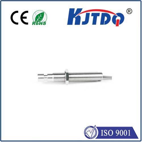
- Standard Shielded (Flush Mountable): The most common type. The coil is partially surrounded by a ferromagnetic shield (metal ring), concentrating the electromagnetic field forward. This allows them to be mounted flush in metal without affecting performance, saving space.
- Unshielded (Non-Flush Mountable): Lack the front shielding ring, resulting in a larger, more diffuse magnetic field and a longer nominal sensing range for a given sensor size. Crucially, they cannot be installed flush in metal; they require a surrounding clearance area.
- Analog Inductive Sensors: Instead of a simple ON/OFF switch, these provide a continuously variable output signal (e.g., 4-20mA, 0-10V) proportional to the distance of the target from the sensor face. Essential for precise position monitoring or thickness measurement.
- Factor 1 Sensors: Specifically designed to provide the same sensing range for both mild steel and common non-ferrous metals like aluminum or copper. Eliminates the need for recalibration or range reduction when switching target materials.
- High-Temperature Sensors: Utilize specialized components and designs to operate reliably in extreme environments like foundries or near furnaces.
- Slot/Window Sensors: Feature a U-shaped or slot design where the target passes through the sensor. Ideal for detecting small parts, verifying presence/absence, or counting objects on a conveyor.
Where Inductive Pickup Sensors Reign Supreme: Applications Galore
The combination of ruggedness, reliability, and non-contact operation makes inductive proximity sensors indispensable across countless industries:
- Object Detection & Presence Verification: Confirming parts are in place on fixtures, pallets, or conveyors before machining, assembly, or packaging.
- Position Sensing: Detecting the end-of-travel of cylinders, verifying the open/closed state of valves or doors, monitoring camshaft/crankshaft position in engines (though specialized variants exist).
- End-of-Stroke Detection: Reliably signaling when a pneumatic or hydraulic cylinder has fully extended or retracted.
- Speed Monitoring & Counting: Detecting gear teeth, encoder wheels, or bolt heads to measure rotational speed (RPM) or count passing objects.
- Machine Safety: Part of safety interlocks to ensure guards are closed before a machine cycle starts.
- Metal Detection: Sorting applications or verifying metal content in products.
- Fill Level Control (Metal Containers): Detecting the presence of a metal piston or float in tanks.
Why Choose Inductive Proximity Sensors?
Compared


