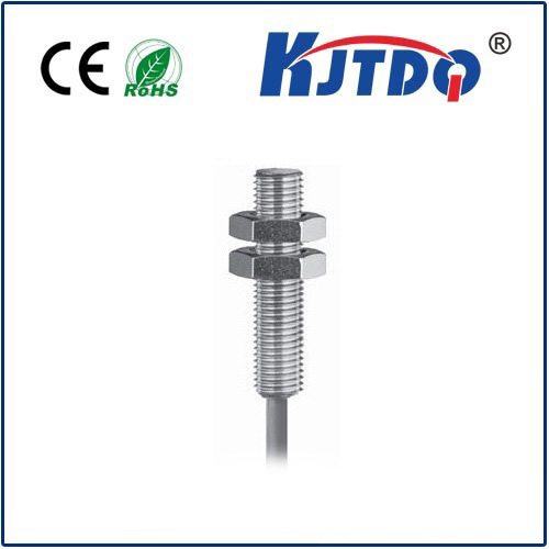
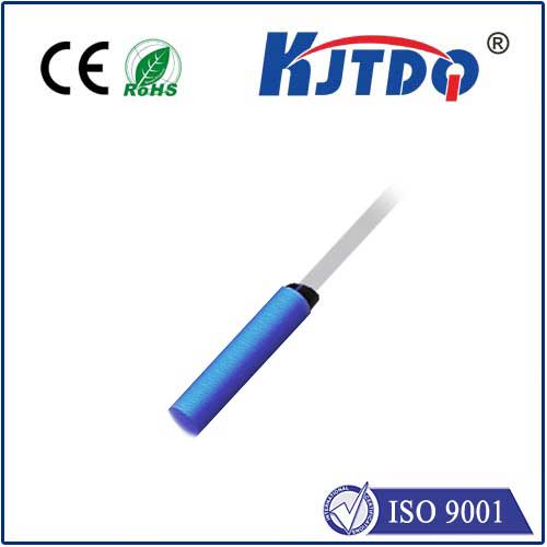
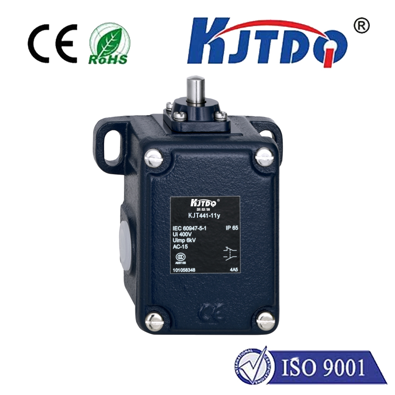
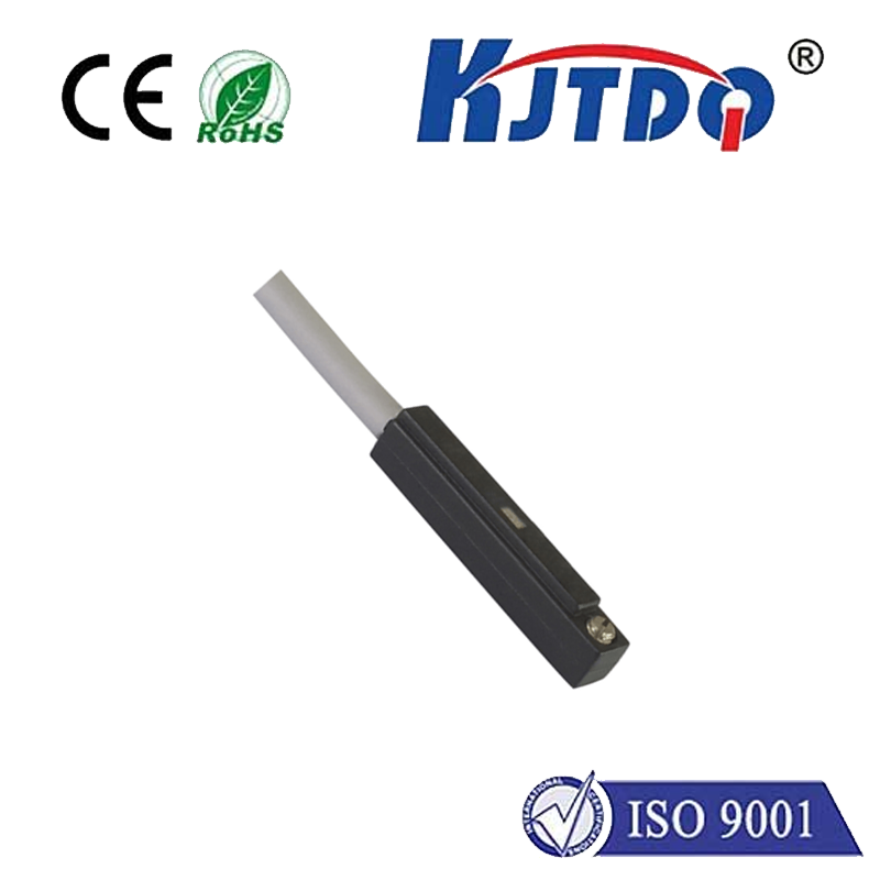
hydraulic cylinder proximity sensors
- time:2025-06-13 02:30:40
- Click:0
Hydraulic Cylinder Proximity Sensors: The Key to Precision Control & System Protection
In the demanding world of hydraulics, where immense forces meet intricate control, knowing the exact position of a cylinder’s piston rod is often non-negotiable. Blind operation isn’t just inefficient; it can be dangerous and costly. This is where the unsung heroes of precise motion control step in: hydraulic cylinder proximity sensors. These compact, robust devices provide the crucial feedback needed for automation, safety, and optimal performance. But how do they work, and why are they indispensable in modern hydraulic systems? Let’s delve into the world of magnetic field detection and position sensing.
Moving beyond rudimentary mechanical switches or cumbersome external limit arms, proximity sensors offer a non-contact solution for detecting the position of the piston rod within the cylinder barrel. Their core principle relies on sensing the presence of a specifically engineered target – typically a ring magnet embedded in the piston or a ferrous metal band attached to the rod. When this target passes within the sensor’s detection range, it triggers a state change in the sensor’s output signal.

For hydraulic cylinders, inductive proximity sensors reign supreme. Here’s the gist:
- Generating the Field: The sensor head contains an oscillator coil that generates a high-frequency electromagnetic field.
- Target Interaction: When a metallic target (like the magnet band or piston) enters this field, it induces small electrical currents called eddy currents within the metal.
- Field Dampening: These eddy currents create their own opposing magnetic field, which dampens the original field generated by the sensor’s coil.
- Signal Detection: The sensor’s circuitry continuously monitors the strength of the oscillator field. The dampening caused by the target causes a measurable change.
- Output Switch: Once the dampening reaches a preset threshold, the sensor’s solid-state electronic switch activates. This typically changes the output state (e.g., from OFF to ON or vice-versa), sending a signal to the system’s controller (PLC).
Why Proximity Sensors are Revolutionizing Hydraulic Control
The adoption of proximity sensors for cylinder position feedback offers substantial advantages over older methods:
- Non-Contact Operation: Completely sealed within the cylinder or mounted externally without physical touch, they eliminate mechanical wear and tear. This translates directly to extraordinarily long service life, even under millions of cycles. There’s no switch to break or lever to bend.
- Exceptional Reliability & Repeatability: Solid-state electronics offer high immunity to vibration and shock – common in hydraulic environments. They provide highly consistent and precise switching points (repeatability) at the exact same position every time the cylinder strokes.
- Resilience Against Harsh Conditions: Designed specifically for industrial use, quality sensors boast excellent resistance to water, oil, coolant, dust, and high-pressure washdowns. Their construction ensures reliable performance even in the challenging environments typical of hydraulic applications.
- Simplified Installation & Flexibility: Modern sensors come in various form factors, including cylinder manifold blocks (compact valves/sensors mounted directly on the cylinder), retrofit kits for existing cylinders, or standard threaded barrels for external mounting. This flexibility simplifies integration into new designs or upgrading legacy systems.
- High-Speed Detection: Capable of detecting targets moving at very high speeds, making them suitable for rapid-cycle machinery.
- Critical Safety Functions: Providing definitive “end-of-stroke” or “mid-stroke” position confirmation is vital for machine safety interlocks and preventing collisions or over-travel damage.
Key Considerations for Selecting the Right Sensor
Choosing the optimal hydraulic cylinder proximity sensor isn’t universal. Several factors demand attention:
- Target Type: Is it a magnetic band on the rod, the piston itself (if ferrous), or a magnet embedded in the piston? The sensor must be specifically designed to detect the chosen target material effectively. Inductive sensors detect ferrous metals; specialized versions are needed for magnets.
- Operating Environment: Assess exposure levels to fluids (oil type matters), pressure spikes, temperature extremes, and potential chemical exposure. The sensor’s sealing rating (IP67/IP69K is common) and material compatibility (e.g., stainless steel housing, specific seal materials) are critical.
- Mounting Constraints: Cylinder size, available space, and stroke length dictate mounting options. Manifold block sensors offer compactness; external threaded sensors or slot-mounted sensors provide alternatives. Does the cylinder have a pre-machined slot or threaded ports?
- Switching Distance (Sn): Ensure the sensor’s rated operating distance is sufficient to reliably detect the target through the cylinder wall. Don’t operate at the absolute maximum Sn; derate for reliability.
- Output Type & Wiring: Common outputs include PNP (sourcing) or NPN (sinking) transistor switches, and sometimes analog (4-20mA, 0-10V). Ensure compatibility with your PLC or controller input card. M8 or M12 quick-disconnect connectors are standard for ease of maintenance.
- Electrical Specifications: Match voltage supply requirements (typically 10-30V DC) and current ratings to your system.
Installation Best Practices & Ongoing Reliability
Proper installation is paramount for reliable position sensing:
- Precise Positioning: Mount the sensor securely, ensuring it is correctly aligned with the target path. Follow manufacturer guidelines for the optimal distance relative to the Sn value.
- Secure Wiring: Route cables away from moving parts and high-heat sources. Use strain relief at connection points. Shielded cable is often recommended to prevent electrical noise interference, especially near high-power motors or VFDs.
- Protection from Impact: While robust, the sensor head should be positioned to avoid direct physical blows from machinery or flying debris.
- Perform Functional Checks: After installation, cycle the cylinder manually (if safe) to verify the sensor activates reliably at the intended position. Use a multimeter or PLC diagnostics to confirm signal change.
- Routine Inspection: Periodically check sensor mounting integrity and cable condition as part of preventative maintenance. Look for signs of physical damage, fluid ingress, or corrosion at connectors. While inherently long-lasting, environmental extremes can eventually compromise seals.
Hydraulic cylinder proximity sensors are far more than simple on/off switches. They are fundamental components for achieving precise control, enhancing safety protocols, enabling sophisticated automation sequences, and maximizing system uptime. By delivering non-contact, reliable position feedback in the most challenging environments, they empower hydraulic systems to operate smarter, safer, and more efficiently. Whether it’s confirming a clamp is closed, ensuring a press is at the bottom of its stroke, or coordinating the complex dance of multiple cylinders, these sensors provide the essential eyes for the system’s brain. Selecting the right sensor, installing it correctly, and performing basic upkeep ensures the silent precision that modern hydraulics demands becomes a lasting reality.


