pnp sensor
- time:2025-06-12 18:31:18
- Click:0
Demystifying PNP Sensors: The Power of Positive Switching in Automation
Ever peered into a control cabinet, confronted by a tangle of wires leading to various sensors, and wondered, “Which one is which?” Or worse, plugged in a sensor only to find the machine stubbornly ignores it? Often, the culprit lies in a fundamental mismatch between the sensor’s output type and the controller’s expectations. Among the most crucial specifications is whether a sensor uses a PNP or NPN output. Understanding PNP sensors – how they work, where they excel, and how to connect them correctly – is essential knowledge for anyone working with industrial automation, from technicians to engineers. This guide cuts through the confusion, focusing specifically on the role and implementation of PNP-type sensors.
PNP Sensor 101: It’s All About the Output
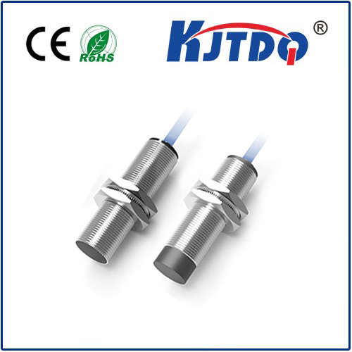
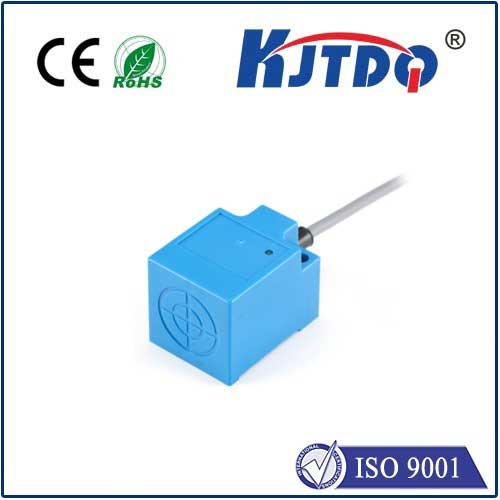
Let’s start simple. A PNP sensor, fundamentally, is an electronic switch integrated into a sensing device (like an inductive proximity sensor, photoelectric sensor, capacitive sensor, or encoder). The “PNP” designation refers specifically to the type of transistor it uses to control its output signal. This output signal tells your PLC (Programmable Logic Controller), machine controller, or other device whether the sensor detects its target (e.g., a metal object is present, a light beam is broken).
Here’s the core principle:
- The “Positive” Switch: A PNP sensor is often called a “sourcing” sensor. When it detects its target (when it’s “ON”), it sources positive voltage (+V, typically 24V DC in industrial settings) to the load (your PLC input module).
- The Circuit Closer: Think of the PNP transistor inside the sensor as a switch connected to the positive supply rail. When active (sensing), this switch closes, connecting the output line directly to the positive voltage supply. This completes the circuit, allowing current to flow out from the sensor’s output terminal, through the load, and back to the power supply’s negative terminal (0V).
- Off State: When the sensor does not detect its target (OFF), the internal PNP transistor is off (open). The output terminal is effectively disconnected from the positive supply, leaving the output in a high-impedance (essentially “floating”) state. No current flows.
Why PNP? The Advantages in Modern Systems

While both PNP and NPN sensor types are prevalent globally, PNP sensors enjoy significant popularity, particularly in Europe and increasingly elsewhere. Here’s why:
- Optimized for Common Sinking PLC Inputs: Many modern PLC input modules are designed as “sinking” inputs. This means their internal circuitry connects to the 0V (common) rail. A PNP (sourcing) sensor naturally complements a sinking input: the sensor sources the positive voltage to the input point, which sinks it to 0V, completing the circuit cleanly. Plugging a PNP sensor into a sinking input is typically straightforward and requires minimal extra components.
- Enhanced Safety Perception: There’s a practical perception, especially in safety circuits (though not exclusively governed by PNP/NPN choice), that having the “live” switching element (the PNP transistor) connecting the output to positive voltage, rather than ground (as in NPN), can offer a slight advantage. If a wire shorts to ground, a PNP output might simply not turn the input ON (fail-safe), whereas a shorted NPN might falsely turn the input ON (a potentially unsafe condition). This is a general tendency and depends heavily on specific wiring and controller design.
- Simplified Fault Finding: In a properly wired system, measuring the voltage at a PNP sensor’s output wire when it should be ON is simple: you expect +V (e.g., ~24V) relative to 0V. When OFF, you expect near 0V. This clear distinction often aids troubleshooting.
- Compatibility with Higher-Level Logic: Since PNP outputs directly provide a positive voltage signal when active, they align naturally with the “active high” logic convention used in many PLC programming environments and electronic circuits.
Where PNP Sensors Shine: Common Applications
PNP sensors form the backbone of countless automated systems. You’ll consistently find them employed in:
- Machine Tooling: Detecting tool position, workpiece presence/clamping, end-of-travel limits.
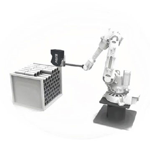
- Material Handling: Monitoring conveyors (package detection, jam detection), palletizing robot end-effector positioning, presence detection on sorting lines.
- Packaging Machinery: Verifying filled bottles/cans, detecting labels, controlling filling heads, ensuring case sealing.
- Assembly Lines: Confirming part placement, checking clamp status, detecting screw presence, verifying robotic pick/place operations.
- Level Sensing: Capacitive or ultrasonic PNP sensors detecting fill levels in tanks or silos.
- Position Feedback: PNP-output encoders providing position and speed data to controllers.
Crucial Wiring: Getting PNP Sensors Connected Right
Correct wiring is non-negotiable. Incorrectly connecting a PNP sensor can lead to malfunction or even damage. Here’s the typical wiring scheme:
- Power: Connect the sensor’s Brown wire (industry standard color coding) to the positive DC supply voltage (+24V).
- Ground: Connect the sensor’s Blue wire to the DC common (0V).
- Output: Connect the sensor’s Black wire (sometimes White or Grey) to your PLC’s input channel (or other load).
- PLC Input Completes the Circuit: The PLC input channel itself must be connected internally to 0V (sinking input) to complete the circuit. When the PNP sensor activates (ON), current flows: +24V (Brown) -> Sensor Internal Circuit -> Output (Black) -> PLC Input -> PLC Internal Circuit to 0V -> Back to Power Supply 0V (Blue).
The Great Debate: PNP vs. NPN Sensors
You can’t discuss PNP sensors without addressing their counterpart, NPN. The key difference is polarity:
- NPN Sensors (“Sinking”): When active (ON), they sink current from the load to 0V. This means they connect their output to the negative supply. They pair naturally with PLC inputs designed as “sourcing” inputs (which provide positive voltage internally).
Choosing between PNP and NPN often boils down to the pre-existing infrastructure and the design of the controller’s input modules:
- Use PNP Sensors with Sinking PLC Inputs. (The safe, common default in many regions/systems).
- Use NPN Sensors with Sourcing PLC Inputs.
Always consult the manuals for both your sensors and your PLC/controller to determine their input/output types before wiring. Trying to connect a PNP sensor directly to a sourcing input designed for NPN will not work correctly without additional interfacing circuitry. The importance of matching sensor output type (PNP sensor sourcing) to controller input type (sinking) cannot be overstated for reliable operation. A simple multimeter check on the expected voltage levels during operation is one of the quickest diagnostics.
The Takeaway: Mastering the “Sourcing” Workhorse
PNP sensors, the sourcing outputs of the industrial sensing world, provide a robust and widely