check

check

check

check
check
check
check
check

check

check
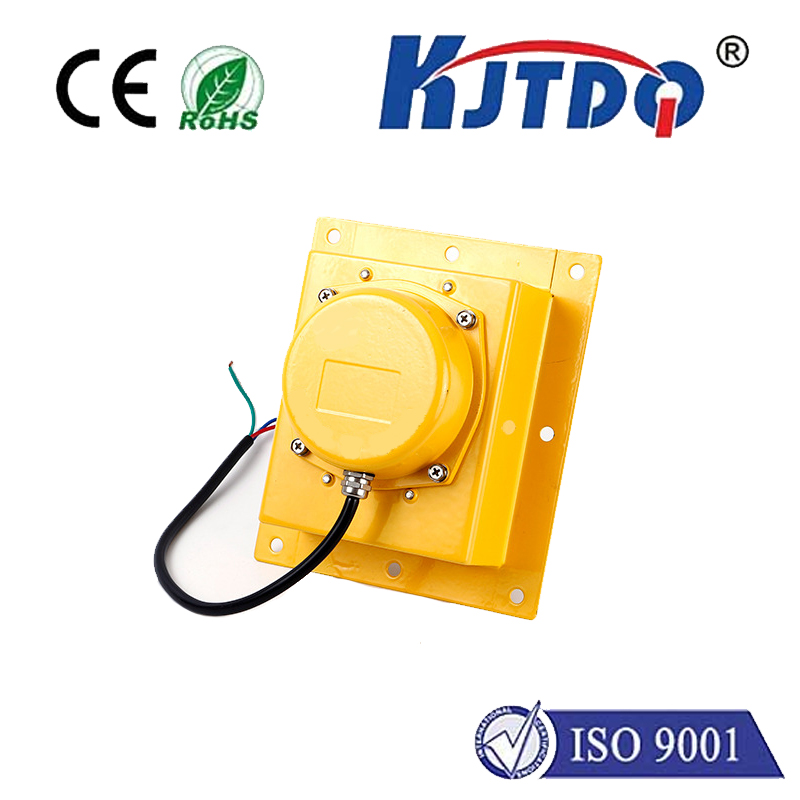
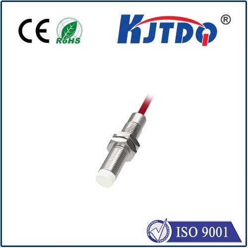
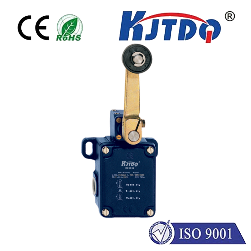
In industrial automation and control systems, the reliable operation of machinery often hinges on precise detection and signal transmission. This is where the critical interplay between a limit switch and a relay becomes indispensable. A limit switch is a fundamental electromechanical device designed to detect the presence or absence of an object, or to monitor the limits of travel of a machine component. Its operation is straightforward: when an actuator (like a lever, roller, or plunger) is physically moved by the target object, it triggers an internal mechanism to open or close an electrical contact. However, the electrical signal generated by a standard limit switch is typically low-power and unsuitable for directly controlling high-current loads such as motors, solenoids, or large lighting systems. This is precisely the role of the relay.
A relay acts as an electrically operated switch. It uses a small electrical signal—like the one from the limit switch—to energize an electromagnet. This magnet then pulls internal contacts together or apart, thereby closing or opening a separate, higher-power circuit. In essence, the limit switch provides the logic or command ("the machine part has reached its position"), and the relay executes the power-handling action ("now turn on the main motor" or "activate the alarm"). This separation is crucial for safety, efficiency, and system design. It allows sensitive, low-voltage control circuits to manage dangerous, high-voltage power circuits without direct connection, protecting both operators and delicate control electronics.
The combination of a limit switch relay system is ubiquitous across industries. In manufacturing, a limit switch on a conveyor belt might detect when a product reaches the end of the line. Upon detection, it signals a relay to stop the conveyor motor. In garage doors, a limit switch determines the fully open and closed positions, with a relay controlling the high-current flow to the door's drive motor. Packaging machines, CNC machinery, and elevator controls all rely on this robust duo for positional control and safety interlocks. A common safety application is as a door interlock: a limit switch confirms a safety guard is securely in place before a relay allows the potentially hazardous machine to start.
Selecting the right components for a limit switch relay setup requires careful consideration. For the limit switch, key factors include the actuator type (lever, roller, plunger), electrical rating (voltage and current it can handle directly), environmental protection (IP rating for dust and moisture), and mechanical life expectancy. The relay must be chosen based on the load it needs to control—its coil voltage must match the control signal from the limit switch, and its contact rating must safely exceed the current and voltage of the main power circuit. Using a relay with an inadequate contact rating is a common point of failure and a serious safety hazard.
Installation and maintenance are straightforward but vital. Limit switches must be mounted securely and aligned accurately to ensure consistent actuation. Wiring should follow all electrical codes, with clear separation between control (limit switch to relay coil) and load (relay contacts to the final device) circuits. Regular maintenance involves checking the limit switch for mechanical wear on the actuator, ensuring it hasn't become loose, and verifying its electrical contacts are not pitted or corroded. Relays should be inspected for signs of arcing on contacts, and their mechanical operation should be tested periodically. A failing limit switch might cause erratic machine behavior, while a welded-shut relay contact can lead to uncontrolled operation—both scenarios underscore the importance of routine checks.
In modern systems, solid-state relays (SSRs) and programmable logic controllers (PLCs) have expanded upon this classic electromechanical principle. SSRs perform the same function as traditional relays but use semiconductors, offering faster switching and longer life with no moving parts. In a PLC system, a limit switch is connected to an input module, and the logic to control an output (which might energize a relay or a motor starter) is programmed in software. This adds immense flexibility but the core concept remains: a discrete sensor (the limit switch) provides a digital signal to control a higher-power process via an intermediary switching device (the relay or its equivalent).
Understanding the symbiotic relationship between a limit switch and a relay is foundational for anyone involved in industrial maintenance, control system design, or automation engineering. This reliable pairing ensures machines operate only as intended, within their physical boundaries, providing both functional control and essential safety. By correctly specifying, installing, and maintaining these components, engineers and technicians guarantee system reliability, protect valuable equipment, and ensure a safe working environment.